


14 - 53
Chapter 14 Common Functions
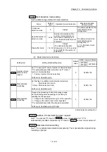
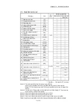
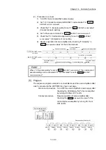
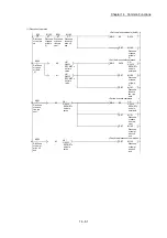
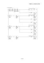
[1] Data that can be set
Data type
Unit
Used
point
Monitoring possibility
MR-J3(W)-B MR-J4(W)-B/
MR-JE-B
1 Effective load ratio
[%]
1 word
2 Regenerative load ratio
[%]
3 Peak load ratio
[%]
4 Load inertia moment ratio
[ 0.1]
5 Model loop gain
[rad/s]
6 Main circuit bus voltage
[V]
7 Servo motor speed
[r/min]
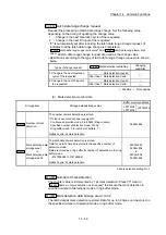
8
Encoder multiple revolution
counter
[rev]
9 Module power consumption
[W]
—
10 Instantaneous
torque
[ 0.1%] —
12
Servo motor thermistor
temperature
[°C]
13 Disturbance
torque
[ 0.1%] —
14 Overload alarm margin
[ 0.1%] —
15 Error excessive alarm margin
[ 16PLS] —
16 Settling
time
[ms]
—
17 Overshoot
amount
[PLS]
—
18 Internal temperature of encoder
[°C]
—
20 Position
feedback
[PLS]
2 words
21
Encoder position within one
revolution
[PLS]
22 Selected droop pulse
[PLS]
23
Module integral power
consumption
[Wh] —
24 Load-side encoder information 1
[PLS]
(Note-4)
(Note-4), (Note-5)
25 Load-side encoder information 2
—
(Note-4)
(Note-4), (Note-5)
26 Z-phase
counter
[PLS]
—
(Note-3)
27
Servo motor side/load-side
position deviation
[PLS] —
(Note-4)
28
Servo motor side/load-side speed
deviation
[ 0.01r/min]
—
(Note-4)
30
Module power consumption (2
words)
[W] —
: Possible, — : Not possible ("0" is stored.)
(Note-1): The motor speed that took the average every 227[ms].
Use the servo amplifiers of version compatible with the monitor of motor speed.
Always "0" if the monitor is executed for the servo amplifier which does not support this
function.
(Note-2): The data set to "Droop pulse monitor selection for controller display" of "
Fully closed loop
function selection 3
(PE10)" is monitored.
(Note-3): It can be monitored when using the linear servo motors.
(Note-4): It can be monitored when using the fully closed control.
(Note-5): It can be monitored when using the synchronous encoder via servo amplifier.
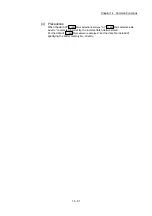
Refer to each servo amplifier instruction manual for details of the data monitored.
Summary of Contents for MELSEC-L Series
Page 2: ......
Page 30: ...MEMO ...
Page 70: ...2 10 Chapter 2 System Configuration MEMO ...
Page 83: ...3 13 Chapter 3 Specifications and Functions MEMO ...
Page 103: ...3 33 Chapter 3 Specifications and Functions MEMO ...
Page 107: ...3 37 Chapter 3 Specifications and Functions MEMO ...
Page 111: ...3 41 Chapter 3 Specifications and Functions MEMO ...
Page 115: ...3 45 Chapter 3 Specifications and Functions MEMO ...
Page 140: ...4 22 Chapter 4 Installation Wiring and Maintenance of the Product MEMO ...
Page 253: ...5 113 Chapter 5 Data Used for Positioning Control MEMO ...
Page 342: ...5 202 Chapter 5 Data Used for Positioning Control MEMO ...
Page 438: ...7 20 Chapter 7 Memory Configuration and Data Process MEMO ...
Page 440: ...MEMO ...
Page 485: ...9 25 Chapter 9 Major Positioning Control MEMO ...
Page 594: ...9 134 Chapter 9 Major Positioning Control MEMO ...
Page 624: ...10 30 Chapter 10 High Level Positioning Control MEMO ...
Page 656: ...11 32 Chapter 11 Manual Control MEMO ...
Page 690: ...12 34 Chapter 12 Expansion Control MEMO ...
Page 798: ...13 108 Chapter 13 Control Sub Functions MEMO ...
Page 866: ...14 68 Chapter 14 Common Functions MEMO ...
Page 884: ...15 18 Chapter 15 Dedicated Instructions MEMO ...
Page 899: ...16 15 Chapter 16 Troubleshooting MEMO ...
Page 1036: ...Appendix 88 Appendices MEMO ...
Page 1039: ......


