


13 - 96
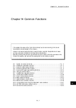
Chapter 13 Control Sub Functions
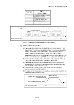
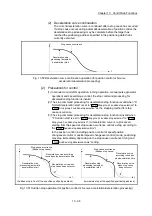
(6) When the movement direction is reversed by a target position change, the
deceleration start flag turns ON.
Time
Operation pattern: Positioning complete (00)
Md.48 Deceleration start flag 0
1
Execution of target position change request
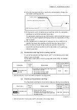
(7) During position control of position-speed switching control, the deceleration
start flag is turned ON by automatic deceleration.
The deceleration start flag remains ON if position control is switched to speed
control by the position-speed switching signal after the deceleration start flag
has turned ON.
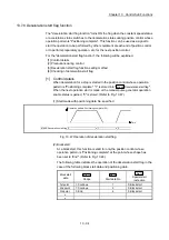
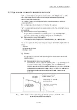
(8) If the condition start of a block start is not made since the condition is not
satisfied, the deceleration start flag turns ON when the shape is "End".
(9) When an interrupt request during continuous operation is issued, the
deceleration start flag turns ON at a start of deceleration in the positioning
data being executed.
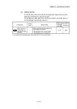
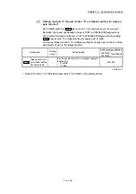
[3] Deceleration start flag function setting method
To use the "deceleration start flag function", set "1" to the following control data
using a sequence program.
The set data is made valid on the rising edge (OFF to ON) of the PLC READY
signal [Y0].
Setting item
Setting
value
Setting details
Buffer memory address
LD77MS2
LD77MS4
LD77MS16
Cd.41
Deceleration start
flag valid
Set whether the deceleration start flag function
is made valid or invalid.
0: Deceleration start flag invalid
1: Deceleration start flag valid
1905 5905
: Refer to Section 5.7 "List of control data" for details on the setting details.
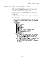
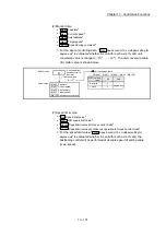
[4] Checking of deceleration start flag
The "deceleration start flag" is stored into the following buffer memory addresses.
Monitor item
Monitor
value
Storage details
Buffer memory address
LD77MS2
LD77MS4
LD77MS16
Md.48
Deceleration start
flag
0: Status other than below
1: Status from deceleration start to next
operation start or manual pulse generator
operation enable
899+100n 2499+100n
n: Axis No.-1
: Refer to Section 5.6 "List of monitor data" for information on the storage details.
Summary of Contents for MELSEC-L Series
Page 2: ......
Page 30: ...MEMO ...
Page 70: ...2 10 Chapter 2 System Configuration MEMO ...
Page 83: ...3 13 Chapter 3 Specifications and Functions MEMO ...
Page 103: ...3 33 Chapter 3 Specifications and Functions MEMO ...
Page 107: ...3 37 Chapter 3 Specifications and Functions MEMO ...
Page 111: ...3 41 Chapter 3 Specifications and Functions MEMO ...
Page 115: ...3 45 Chapter 3 Specifications and Functions MEMO ...
Page 140: ...4 22 Chapter 4 Installation Wiring and Maintenance of the Product MEMO ...
Page 253: ...5 113 Chapter 5 Data Used for Positioning Control MEMO ...
Page 342: ...5 202 Chapter 5 Data Used for Positioning Control MEMO ...
Page 438: ...7 20 Chapter 7 Memory Configuration and Data Process MEMO ...
Page 440: ...MEMO ...
Page 485: ...9 25 Chapter 9 Major Positioning Control MEMO ...
Page 594: ...9 134 Chapter 9 Major Positioning Control MEMO ...
Page 624: ...10 30 Chapter 10 High Level Positioning Control MEMO ...
Page 656: ...11 32 Chapter 11 Manual Control MEMO ...
Page 690: ...12 34 Chapter 12 Expansion Control MEMO ...
Page 798: ...13 108 Chapter 13 Control Sub Functions MEMO ...
Page 866: ...14 68 Chapter 14 Common Functions MEMO ...
Page 884: ...15 18 Chapter 15 Dedicated Instructions MEMO ...
Page 899: ...16 15 Chapter 16 Troubleshooting MEMO ...
Page 1036: ...Appendix 88 Appendices MEMO ...
Page 1039: ......


