


5 - 41
Chapter 5 Data Used for Positioning Control
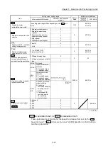
Item
Setting value, setting range
Default
value
Buffer memory address
Value set with GX Works2
Value set with sequence
program
LD77MS2
LD77MS4
LD77MS16
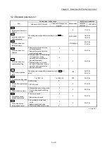
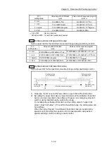
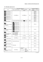
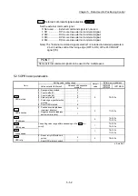
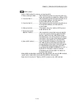
Pr.41
Allowable circular
interpolation error width
The setting value range differs depending on the "
Pr.1
Unit
setting
".
100
60+150n
61+150n
Pr.42
External command function
selection
0: External positioning start
0
0 62+150n
1: External speed change
request
1
2: Speed-position, position-
speed switching request
2
3: Skip request
3
4: High speed input request
4
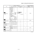
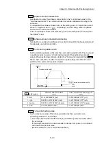
Pr.83
Speed control 10 x multiplier
setting for degree axis
0: Invalid
0
0 63+150n
1: Valid
1
Pr.84
Restart allowable range
when servo OFF to ON
0, 1 to 327680 [PLS]
0: restart not allowed
0
64+150n
65+150n
Pr.89
Manual pulse generator/
Incremental synchronous
encoder input type selection
0: Differential output type
0
0 67
1: Voltage output/open collector
type
1
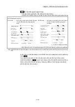
Pr.90
Operation setting for speed-
torque control mode
b0 to b3 Not used
b15 to b12b11 to b8 b7 to b4 b3 to b0
Always "0" is
set to the part
not used.
0000H 68+150n
b4 to b7
Torque initial value
selection
0: Command torque
1: Feedback torque
b8 to
b11
Speed initial value
selection
0: Command speed
1: Feedback speed
2: Automatic selection
b12 to
b15
Condition selection at
mode switching
0: Switching
conditions valid (for
switching control
mode)
1: Zero speed ON
condition invalid
(for switching
control mode)
Pr.95
External command signal
selection
LD77MS16
0: Not used
0
0
69+150n
1: DI1
1
2: DI2
2
3: DI3
3
4: DI4
4
n: Axis No.-1
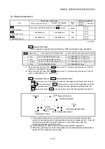
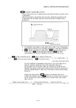
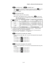
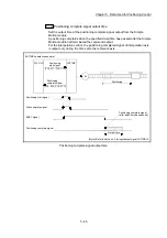
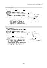
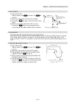
Pr.25
Acceleration time 1 to
Pr.27
Acceleration time 3
These parameters set the time for the speed to increase from zero to the "
Pr.8
Speed limit value
" ("
Pr.31
JOG speed limit value
" at JOG operation control) during a
positioning operation.
Summary of Contents for MELSEC-L Series
Page 2: ......
Page 30: ...MEMO ...
Page 70: ...2 10 Chapter 2 System Configuration MEMO ...
Page 83: ...3 13 Chapter 3 Specifications and Functions MEMO ...
Page 103: ...3 33 Chapter 3 Specifications and Functions MEMO ...
Page 107: ...3 37 Chapter 3 Specifications and Functions MEMO ...
Page 111: ...3 41 Chapter 3 Specifications and Functions MEMO ...
Page 115: ...3 45 Chapter 3 Specifications and Functions MEMO ...
Page 140: ...4 22 Chapter 4 Installation Wiring and Maintenance of the Product MEMO ...
Page 253: ...5 113 Chapter 5 Data Used for Positioning Control MEMO ...
Page 342: ...5 202 Chapter 5 Data Used for Positioning Control MEMO ...
Page 438: ...7 20 Chapter 7 Memory Configuration and Data Process MEMO ...
Page 440: ...MEMO ...
Page 485: ...9 25 Chapter 9 Major Positioning Control MEMO ...
Page 594: ...9 134 Chapter 9 Major Positioning Control MEMO ...
Page 624: ...10 30 Chapter 10 High Level Positioning Control MEMO ...
Page 656: ...11 32 Chapter 11 Manual Control MEMO ...
Page 690: ...12 34 Chapter 12 Expansion Control MEMO ...
Page 798: ...13 108 Chapter 13 Control Sub Functions MEMO ...
Page 866: ...14 68 Chapter 14 Common Functions MEMO ...
Page 884: ...15 18 Chapter 15 Dedicated Instructions MEMO ...
Page 899: ...16 15 Chapter 16 Troubleshooting MEMO ...
Page 1036: ...Appendix 88 Appendices MEMO ...
Page 1039: ......


