

CX1000 Installation and
Connection Guide
IM 04L31A01-73E 3rd Edition
Yokogawa Electric Corporation
Thank you for purchasing the CX1000.
This manual contains simple explanations about how to install and connect
the CX1000. For more information about the procedures described herein,
safety precautions, and the CX1000 functions and operation, please refer to
the PDF manual found on the provided CD-ROM.
Installation Procedure
1. Cut the instrument panel according to the diagram below.
For the panel cut dimensions when installing multiple units closely
together, see the
CX1000 User’s Manual IM 04L31A01-03E
found on
the provided CD-ROM.
Panel Cut Diagram
When installing
a single unit
137
+2
0
137
+2 0
Unit: mm
2. Insert the CX1000 into the front of the panel.
3. Using the mounting brackets that came with the package, attach the
CX1000 to the panel as shown in the following figure.
First, attach the two mounting brackets and temporarily fasten the
attachment screws. Next, fix the CX1000 in place by tightening the
attachment screws with the appropriate torque (0.7 to 0.9 N-m.). As you
fasten the screws, press the mounting bracket against the case so that
they are in contact with each other.
Screw temporarily
Fix in place
Front
Panel
Panel
Mounting bracket
Mounting bracket
Torque driver
(flat blade)
Attachment screw
Case
In contact
with each other
(The figure shows the case
when the mounting brackets
are used on the top and bottom
of the case.)
Attachment screw
For details about the CX1000 external dimensions, installation environment,
and more, please refer to the
CX1000 User's Manual (IM 04L31A01-01E)
.
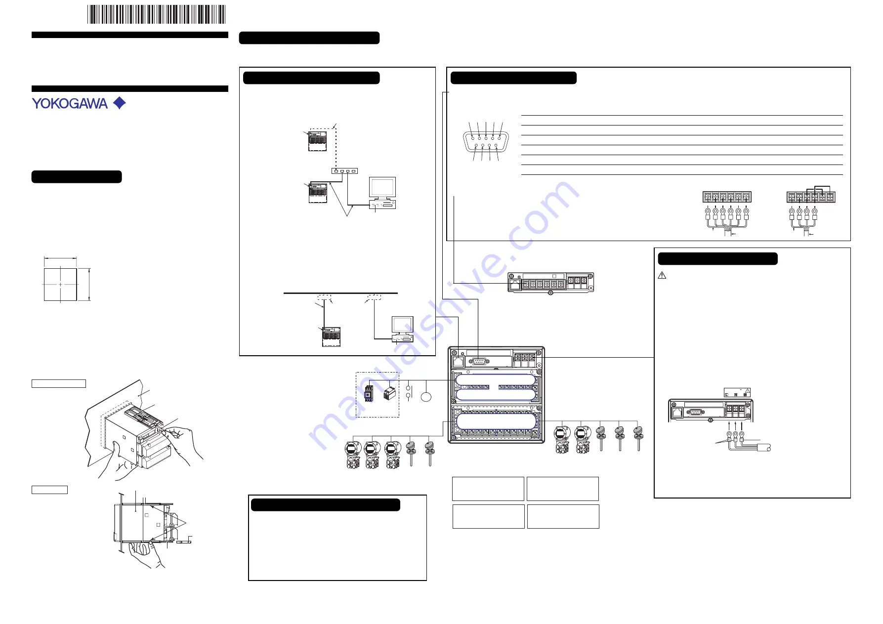
Connection Types and Procedures
There are various terminals and connectors on the rear panel of the CX1000. Connecting them to peripheral devices allows you to perform control and measurement operations. Below are the names of each connector and terminal, as
well as connection procedures.
FG SG
SDB
SDA
RDB
RDA
Shield potential
Two-wire
Shield
FG SG
SDB
SDA
RDB
RDA
Shield potential
Four-wire
Shield
Magnet
switch
SSR
R1
5 universal measurement inputs
6 universal measurement inputs
Control/measurement input
terminal block
Control output terminal block
Option terminal block
or
Option terminal block (one of the following)
Measurement alarm output
+ remote input/output
(/A6R option)
Measurement alarm output
+ FAIL/memory end output
(/A4F option)
Measurement alarm
FAIL/memory
end remote
input/output (/A4FR option)
Measurement alarm output
(/A6 option)
Contact
input
6 inputs
Contact
output
6 outputs
Controls and Switch
With an RS-422/485
CX1000 Rear Panel
Connecting Input/Output Connectors
When connecting various input/output connectors for control or
measurement, proceed as described below.
Connect the crimp connectors (for 4-mm screws) to the terminal
strip.
1. Turn off the CX1000 and remove the terminal cover.
2. Wire the signal wires to the terminals.
Attach the terminal cover and secure it with screws.
3rd Edition: May 2007(YK)
All Right Reserved, Copyright © 2001
Yokogawa Electric Corporation
With an RS-232
Connecting the Ethernet Interface
•
When only Connecting to a Hub
Connect the CX1000 and the PC through a HUB as shown in the
following figure.
PC
Ethernet NIC
Hub
10BASE-T
straight cable
10BASE-T straight cable
Ethernet
interface connector
Ethernet
interface connector
(Use a hub to connect
multiple units.)
CX
CX
•
When Connecting to a Preexisting Network
The following figure illustrates an example in which the CX1000 and
a PC are connected to the network. When connecting the CX1000 or
the PC to a preexisting network items such as the transfer rate and
connector type must match. For details, consult your system or
network administrator.
PC
Ethernet NIC
10BASE-T straight cable
Network
Ethernet
interface connector
CX
10BASE-T adapters
(hubs, routers, etc.)
Connecting the Power Supply
When using electrical wiring, be certain to follow the safety
recommendations prescribed in the CX1000 User's Manual.
Use a power supply that meets the following conditions:
Rated supply voltage:
100 to 240 VAC
Supply voltage range used:
90 to 132, 180 to 264 VAC
Rated supply voltage frequency:
50/60 Hz
Permitted supply voltage frequency range:
50/60 Hz
±
2%
Maximum power consumption:
39 VA (100 V), 51 VA (240 V)
1. Turn OFF the CX1000 and open the cover (transparent) for the
power supply wires.
2. Connect the power cord and the protective ground cord to the power
supply terminals.
100-240V AC
50/60Hz 51VA MAX
Power cord
Protective grounding cord
3. Close the cover (transparent) for the power supply wires and secure
it in place with screws.
For the power supply specifications and connection method of the 24VDC/AC
power supply option, please refer to the CX1000 User's Manual.
*
4
L
3
1
A
1
7
3
E
0
3
*
Pin No. Signal Name
Signal Meaning
2
RD (Received Data)
Received data from the connected device. Input signal.
3
SD (Send Data)
Send data to the connected device. Output signal.
5
SG (Signal Ground)
Signal ground.
7
RS (Request to Send) Handshaking signal used when receiving data from the connected device. Output signal.
8
CS (Clear to Send)
Handshaking signal used when sending data to the connected device. Input signal.
* Pins 1, 4, 6, and 9 are not used.
Connecting the Serial Interface
•
RS-232 (When Connecting to a Computer or Other Such Devices)
Verify that the CX1000 has an RS-232 connector, and then connect a serial cable to it. Connect the other end of the serial cable to the other device.
2
1
3 4 5
6 7
9
8
•
RS-422/485 (When Connecting to a PLC, Temperature Controller or
Other Such Devices)
Verify that the CX1000 has an RS-422/485 connector, and then connect the crimp
connectors (for 4-mm screws) to the terminal strip as illustrated on the right. Do not
expose more than 5 cm of the cable surface from the shield.


