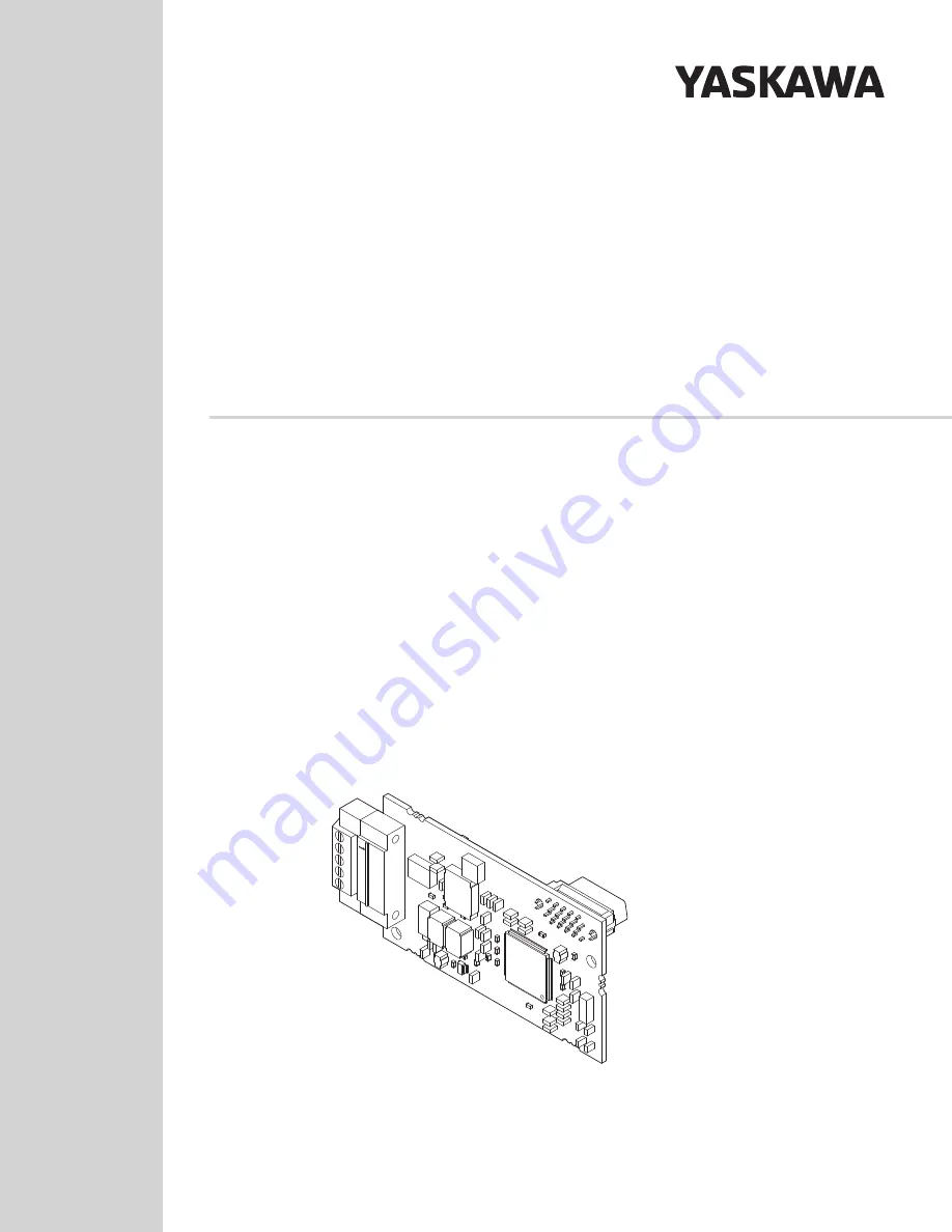
background image

CC-Link 

通信

安川インバータ オプション

取扱説明書

形式

SI-C3

CC-Link

YASKAWA AC Drive Option

Type: SI-C3

Installation Manual

To properly use the product, read this manual thoroughly and retain 
for easy reference, inspection, and maintenance. Ensure the end user 
receives this manual.

製品を安全にお使いいただくために,本書を必ずお読みください。
また,本書をお手元に保管していただくとともに,最終的に本製品をご使用になる
ユーザー様のお手元に確実に届けられるよう,お取り計らい願います。

COSMOS(140×182)(和英併記)新CI 

改版<1> 2011.8

MANUAL NO.  TOBP C730600 83C

Summary of Contents for CC-Link

Page 1: ...AC Drive Option Type SI C3 Installation Manual To properly use the product read this manual thoroughly and retain for easy reference inspection and maintenance Ensure the end user receives this manua...

Page 2: ...the prior written permission of Yaskawa No patent liability is assumed with respect to the use of the information contained herein Moreover because Yaskawa is constantly striving to improve its high q...

Page 3: ...ion Manual 3 Table of Contents 1 PREFACE AND SAFETY 4 2 OVERVIEW 8 3 RECEIVING 9 4 OPTION COMPONENTS 10 5 INSTALLATION PROCEDURE 13 6 RELATED DRIVE PARAMETERS 32 7 BASIC FUNCTIONS 35 8 CC LINK DATA TA...

Page 4: ...PLIED IS OFFERED YASKAWA assumes no liability for any personal injury property damage losses or claims arising from misapplication of its products u Applicable Documentation The following manuals are...

Page 5: ...essages could result in serious or possibly even fatal injury or damage to the products or to related equipment and systems Note Indicates supplemental information that is not related to safety messag...

Page 6: ...g to the instructions described in this manual The diagrams in this manual are provided as examples only and may not pertain to all products covered by this manual The products and specifications desc...

Page 7: ...ation of the product made by the user Do not modify this product NOTICE Do not modify the drive or option circuitry Failure to comply could result in damage to the drive or option and will void warran...

Page 8: ...with the products in Table 1 Table 1 Compatible Products Note Refer to the option package labeling in the field designated PRG four digit number or the option labeling in the field designated C N S fo...

Page 9: ...ame Refer to Figure 2 on page 10 for details Contact the distributor where the option was purchased or contact Yaskawa or a Yaskawa representative about any problems with the option u Contents and Pac...

Page 10: ...and Fault LED Display on Option Side on page 52 for details on the LEDs 2 Connect the provided ground wire during installation Installation on GA700 and GA800 drives does not require the ground wire...

Page 11: ...L RUN Green ON Normal operation Receiving data normally OFF Timed out Timed out waiting to receive Logging onto the network During reset L ERR Red ON CRC error CRC error Station address setting error...

Page 12: ...ation address Range 1 to 64 unique to the network If set to 0 the L ERR light will turn on and a Station Address Error AEr will occur RD Red ON Detecting data received Detecting data that was received...

Page 13: ...FF measure for unsafe voltages to confirm the drive is safe WARNING Electrical Shock Hazard Do not operate equipment with covers removed Failure to comply could cause death or serious injury The diagr...

Page 14: ...cause ESD damage to circuitry Never connect or disconnect the motor from the drive while the drive is outputting voltage Improper equipment sequencing could damage the drive Do not connect or operate...

Page 15: ...ring options differ depending on the drive model Refer to Table 5 to check the procedures for installing and wiring options on a drive Table 5 Procedures for Installing and Wiring Options on a Drive P...

Page 16: ...loded view of the drive with the option and related components for reference in the installation procedure Figure 5 Figure 5 Drive Components with Option A Insertion point for CN5 connector I Ground w...

Page 17: ...t all power to the equipment and wait for at least the time specified on the warning label The internal capacitor remains charged even after the drive is de energized The charge indicator LED will ext...

Page 18: ...the appropriate position on the drive front cover C Figure 7 Figure 7 Affix the LED Label 3 Insert the option card B into the CN5 A L connector on the drive and fasten it into place using one of the i...

Page 19: ...d of the ground wire I to the remaining ground terminal and installation hole on the option B using the last remaining provided screw H Tighten both screws to 0 5 to 0 6 N m 4 4 to 5 3 in lb Figure 9...

Page 20: ...gh openings on the front cover of some models Remove the perforated tabs on the left side of the front cover as shown in Figure 11 A to create the necessary openings on these models Refer to the Perip...

Page 21: ...ing and other electrical and power lines Ensure the cable end is firmly connected see Table 6 Refer to Communication Cable Topology on page 30 for details 7 Reattach the drive front covers C F and the...

Page 22: ...e functions correctly Refer to Figure 13 for an exploded view of the drive with the option and related components for reference in the installation procedure Figure 13 Figure 13 Drive Components with...

Page 23: ...ctrical Shock Hazard Do not inspect connect or disconnect any wiring while the drive is energized Failure to comply will cause death or serious injury Before servicing disconnect all power to the equi...

Page 24: ...val NOTICE Damage to Equipment Observe proper electrostatic discharge ESD procedures when handling the option drive and circuit boards Failure to comply could cause ESD damage to circuitry Figure 15 F...

Page 25: ...ht side of the drive using the temporary placement holes Refer to the manual packaged with the drive for details on removing the LED Status Ring board NOTICE Do not remove the LED Status Ring board ca...

Page 26: ...and a ground wire for installation on other product series Do not use the ground wire or the extra screw Figure 17 Figure 17 Insert the Option Card 5 Select the proper CC Link dedicated communication...

Page 27: ...n the front cover or the LED Status Ring board and the drive Failure to comply could cause erroneous operation 7 Reattach the drive front cover D and the keypad F Figure 18 Figure 18 Replace the Front...

Page 28: ...19 Figure 19 CC Link Cable Diagram Item Specifications Cable Type triple core shielded twisted pair cable External Diameter 8 0 mm maximum Drain Wire 20 lines 0 18 mm or 24 lines 0 18 mm Electrical Ch...

Page 29: ...page 31 2 Make sure that the FG terminal on the master drive is grounded properly 3 Connect the provided ground wire for installations on 1000 series drives The ground wire is not necessary for insta...

Page 30: ...utions to ensure that each cable is properly connected and that wire insulation is not accidentally pinched into the option modular connector CN1 1 The option must be configured with a termination res...

Page 31: ...on connected in a CC Link network the termination resistor needs to be installed on that CC Link Option Cut the ring lugs from the termination resistor leads and then loosen the DA and DB terminals an...

Page 32: ...s the input method for the Run command 0 Keypad 1 Digital Input 2 Memobus Modbus Communications 3 Option PCB Default 1 Range 0 to 3 b1 18 2 Voltage Reference Source Selects the voltage reference input...

Page 33: ...bled 9 Default 0 Range 0 1 F6 07 MultiStep Ref Priority Select 0 MultiStep References Disabled 1 MultiStep References Enabled Default 0 Range 0 1 F6 08 Comm Parameter Reset Initialize Selects whether...

Page 34: ...will differ as follows Name Torque Reference Torque Limit Selection from Communications Option Description Enables or disables the torque reference or torque limit 0 Enabled 1 Disabled 8 Control meth...

Page 35: ...rive the CC Link Option is connected to for a list of monitor codes and drives u Reading and Setting Parameters The PLC can write drive parameters read drive data and operation status and change setti...

Page 36: ...setting 4 0C04H Register number setting 5 0C05H Register number setting 6 0C06H Register number setting 7 0C07H Register number setting 8 0C08H Register number setting 9 0C09H Register number setting...

Page 37: ...of register number 1200 H Example 2 When reading the parameter of the MEMOBUS register number 1500H with the register number setting 9 Write the register number 1500H that you want to set to register...

Page 38: ...ault Reset RY4 Terminal S5 Function Multi function input H1 05 H1 05 3 Multi Step Speed 1 RY5 Terminal S6 Function Multi function input H1 06 H1 06 4 Multi Step Speed 2 RY6 Terminal S7 Function Multi...

Page 39: ...Frequency Reference 2 Sets the frequency in the remote register RWW1 to parameter d1 01 Frequency Reference 1 and as the drive s main frequency reference at the same time Note If the frequency refere...

Page 40: ...g Run RX3 Speed Agree ON Output frequency is between frequency reference and the detection width set to L4 02 RX4 During Stall Prevention RX5 During Undervoltage RX6 YASKAWA AC Drive 1000 Series Termi...

Page 41: ...longer present RX10 to 19 Reserved RX1A Error ON Fault occurred on the drive side RX1B Remote Station Ready ON Drive is ready to operate RX1C to 1F Reserved 1 Terminals will differ depending on the mo...

Page 42: ...e the command code Triggered by the rising edge of the signal RY10 Terminals M1 M2 Function Multi Function Relay Output 1 terminal M1 M2 RY11 Terminals P1 PC Function 1 Multi Function Photocoupler Rel...

Page 43: ...ring MC ON RX7 Terminals P2 PC Function 1 Multi function output H2 03 H2 03 6 Energy Saving Unit Ready RX8 Momentary Power Loss Ride Thru Recovery from Momentary Power Loss RX9 ComCtrlstatus NetCtrlst...

Page 44: ...to be displayed by the monitor RYC Monitor Execute Request RWW1 Frequency Setting Specifies the source of the frequency reference RYD Frequency Reference 1 RYE Frequency Reference 2 RWW2 Command Code...

Page 45: ...Complete RWR3 Read Data Data is set according to the command code Remote Register Name Description Request Flag RWW0 Monitor Code Sets the code number of the items to be displayed by the monitor Once...

Page 46: ...2h Command code error 03h Data setting range error RXF Command Code Execute Complete RWR3 Read Data Data is set according to the command code Drive Type Name Terminal Drive Model YASKAWA AC Drive 1000...

Page 47: ...s Multi Function Digital Output 2 M3 M4 All drives Multi Function Digital Output 3 M5 M6 All drives 1 Terminals will change to M3 M4 depending on the model type of CIMR B Refer to the drive instructio...

Page 48: ...momentary power loss interrupt communications Table 18 Fault Display and Possible Solutions Keypad Display Fault Name bUS Option Communication Error After establishing initial communication the connec...

Page 49: ...perly connected Cause Possible Solution The option card installed into port CN5 A is incompatible with the drive Connect the option to the correct option port Note PG option cards are supported by opt...

Page 50: ...N5 C when connecting only one PG option Keypad Display Fault Name oFb02 Option Fault CN5 B Two identical options are connected at the same time Cause Possible Solution An option of the same type is al...

Page 51: ...ster side Check communications at start up and correct programming errors Communication circuitry is damaged Perform a self diagnostics check If the problem continues replace either the control board...

Page 52: ...controller PLC CPU stopped Did a momentary power loss interrupt communications n Faults that Occur with a Single Drive The example below demonstrates how to read the LED display on the front cover of...

Page 53: ...d Problem with the hardware Try cycling the power Replace the CC Link Option if the problem continues Problem with the hardware Try cycling the power Replace the CC Link Option if the problem continue...

Page 54: ...Figure 28 Connecting Multiple Drives on the Same Network Problem with the hardware Try cycling the power Replace the CC Link Option if the problem continues Data cannot be received CC Link communicati...

Page 55: ...UN SD RD L ERR L RUN SD RD L ERR L RUN SD RD L ERR Because L RUN after Station 2 is off either the comm line between Station 1 and Station 2 is disconnected or the connector has come loose Make sure c...

Page 56: ...R The CC Link Option connected to Station 2 is experiencing electrical noise interference L RUN is sometimes off Make sure that the CC Link Options drives and master device are all grounded properly L...

Page 57: ...mark When using drives displaying the CE mark in combination with other devices it is ultimately the responsibility of the user to ensure compliance with CE standards Verify that conditions meet Europ...

Page 58: ...O AI AO SI Figure 31 Figure 31 Option Installation for CE Compliance PG DI DO AI AO SI A Braided shield cable C Cable clamp conductive B Metal panel C B A L1 L2 L3 L1 L2 L3 R CN5 B CN5 C CN5 A CN5 B C...

Page 59: ...on Complies with CC Link Ver 1 10 Station Type Remote device station No of Occupied Stations 1 Communication Speed 156 kbps to 10 Mbps Ambient Temperature 10 C to 50 C 14 F to 122 F Humidity up to 95...

Page 60: ...November 2018 4 All Addition Applicable product series Revision Reviewed and corrected entire documentation Back cover Revision Address June 2018 3 Address in Japanese version July 2017 2 Back cover...

Page 61: ...0099 Fax 66 2 017 0799 http www yaskawa co th YASKAWA ELECTRIC CHINA CO LTD 22F Link Square 1 No 222 Hubin Road Shanghai 200021 China Phone 86 21 5385 2200 Fax 86 21 5385 3299 http www yaskawa com cn...

Reviews: