background image

Installation, Operating & 
Maintenance Instructions 


980029EB 

Edition 2019-10-11 


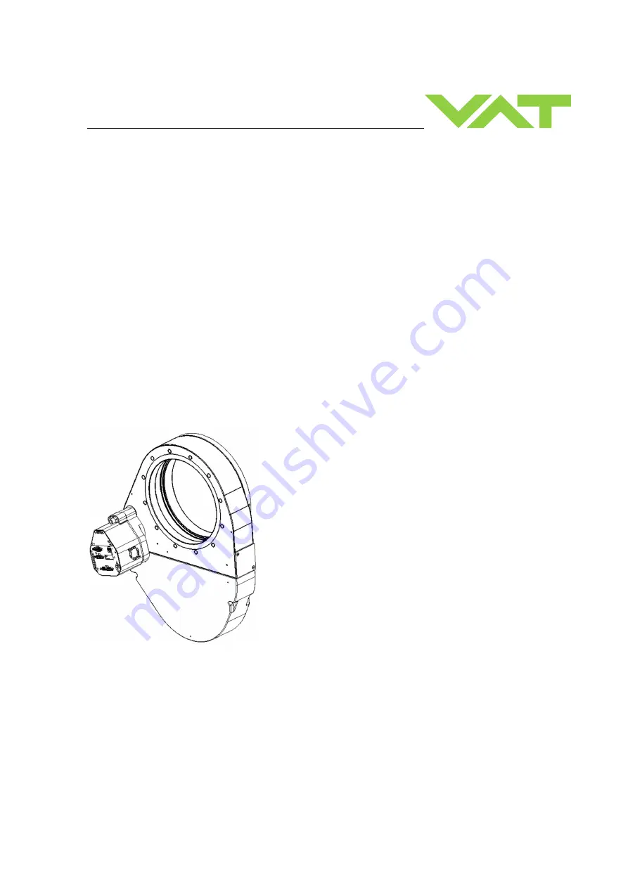
Pendulum control & isolation valve 

with Logic interface 


Series 653 
DN 100-250 mm (I.D. 4“ - 10") 


This manual is valid for the valve ordering number(s): 
 
653 . . - . .GE - . . . . 

(2 sensor inputs / analog outputs) 

653 . . - . .AE - . . . . 

(2 sensor inputs / analog outputs / 

±

15V SPS) 

653 . . - . .HE - . . . . 

(2 sensor inputs / analog outputs / PFO) 

653 . . - . .CE - . . . . 

(2 sensor inputs / analog outputs / 

±

15V SPS / PFO) 

 
SPS = Sensor Power Supply 

PFO = Power Failure Option 


configured with firmware :  F01.0C.28.xx 


Sample picture 
 

Summary of Contents for 653 - AE Series

Page 1: ...0 250 mm I D 4 10 This manual is valid for the valve ordering number s 653 GE 2 sensor inputs analog outputs 653 AE 2 sensor inputs analog outputs 15V SPS 653 HE 2 sensor inputs analog outputs PFO 653 CE 2 sensor inputs analog outputs 15V SPS PFO SPS Sensor Power Supply PFO Power Failure Option configured with firmware F01 0C 28 xx Sample picture ...

Page 2: ... duplicated or distributed without written permission from VAT Offenders are liable to pay damages The original VAT firmware and updated state of the art versions of the VAT firmware are intended for use with VAT products The VAT firmware contains a limited time unlimited user license The VAT firmware may not be used for purposes other than those intended nor is it permitted to make copies of the ...

Page 3: ...rocedure 21 4 2 4 Tightening torque 22 4 2 5 Mounting with centering rings 22 4 2 6 Mounting with O ring in grooves 23 4 2 7 Admissible forces 24 4 2 8 Requirements to sensor connection 24 4 3 Electrical connection 25 4 3 1 Ground connection 26 4 3 2 Power and Sensor supply concepts 27 4 3 3 Digital Input Output and analogue output connections 33 4 3 4 Connection with switches over power supply co...

Page 4: ...Operation under increased temperature 75 5 10 Behavior In case of compressed air pressure drop 75 6 Trouble shooting 76 6 1 1 Controller Display 76 6 1 2 Error numbers 76 6 1 3 Error code 76 7 Maintenance 78 7 1 Maintenance intervals 78 7 2 Maintenance procedures 79 7 2 1 Replacement of isolation seals and valve cleaning 80 7 2 2 Replacement of actuator shaft seals 83 7 2 3 Replacement of Option b...

Page 5: ...Use product for clean and dry vacuum applications only Other applications are only allowed with the written permission of VAT 1 3 Used abbreviations Abbreviation Description CPA Control Performance Analyzer PFO Power Failure Option SFS Sensor Full Scale SPS Sensor Power Supply ADC Analog to digital converter 1 4 Related documents Product Data Sheet Dimensional Drawing IOMI Heating device if valve ...

Page 6: ...VDC 5 1200 mA max connector POWER connector SENSOR Sensor power supply 2 β 653 G 653 H Input Output 24 VDC resp 15 VDC same as input but 2 0 A max at 15 VDC 1 5 A max at 24 VDC connector POWER connector SENSOR Actuator type Stepper motor with servo control Ingress Protection IP30 1 Internal overcurrent protection by a PTC device 2 Refer to chapter Sensor supply concepts for details 3 PFO Power Fai...

Page 7: ...ad valve closed adjustable with CPA 4 0 valve opened adjustable with CPA 4 0 connector POWER max 70 V 0 1 A connector POWER Digital inputs 4 voltage control contact control 5 24V 2 10 mA 3 3V 2 mA connector INTERFACE Digital outputs 4 Input voltage Input current max 70 V max 0 1 A connector INTERFACE Analog outputs 4 0 10 VDC 1 mA max connector INTERFACE PFO 5 battery pack 653 C 653 H Charging tim...

Page 8: ...s typ 0 45 s typ 0 9 s typ 0 5 s typ 0 9 s typ 0 5 s typ Opening time throttling only full stroke 0 7 s typ 0 4 s typ 0 8 s typ 0 45 s typ 0 9 s typ 0 5 s typ 0 9 s typ 0 5 s typ Closing time throttling isolation full stroke 3 s typ 3 s typ 3 s typ 3 s typ Opening time throttling isolation full stroke 4 s typ 4 s typ 4 s typ 4 s typ 4 Refer to chapter Schematics for details 5 PFO Power Failure Opt...

Page 9: ...cycles open closed open Throttling cycles open max throttle open 200 000 unheated and under clean conditions 1 000 000 unheated and under clean conditions Admissible operating temperature 10 C to 120 C Mounting position horizontally only Wetted materials Body 653 A Aluminum 3 3211 AA6061 Body 653 H Aluminum 3 3211 AA6061 hard anodized Body 653 I Aluminum 3 3211 AA6061 nickel coated Pendulum plate ...

Page 10: ...250 10 65348 Max differential pressure on plate during isolation 1200 mbar in either direction 1200 mbar in either direction 1200 mbar in either direction 1200 mbar in either direction Max differential pressure on plate during opening and throttling 30 mbar 10 mbar 5 mbar 5 mbar Min controllable conductance N2 molecular flow Typ 2 l s Typ 4 l s Typ 7 l s Typ 10 l s Dimensions Refer to dimensional ...

Page 11: ...tion Operating Maintenance Instructions are an integral part of a comprehensive documentation belonging to a complete technical system They must be stored together with the other documentation and accessible for anybody who is authorized to work with the system at any time 2 2 Danger levels DANGER High risk Indicates a hazardous situation which if not avoided will result in death or serious injury...

Page 12: ...tions WARNING Unqualified personnel Inappropriate handling may cause serious injury or property damage Only qualified personnel are allowed to carry out the described work 2 4 Safety labels Label Part No Location on valve T 9001 156 On protective foil covering of valve opening ...

Page 13: ...13 103 3 Design and Function 3 1 Design 1 Plate seal 7 Rotary feed through seals 2 Body seal 8 Pendulum plate 3 Shaft feed through seals 9 Sealing ring 4 Bonnet seal 10 Bonnet 5 Actuator 11 Body 6 Integrated controller 12 Body Flange 12 1 2 3 4 10 5 11 9 8 7 6 ...

Page 14: ...a stepper motor An encoder monitors the position This principle ensures fast and accurate process pressure control For opening or control the sealing ring is lifted pneumatically by compressed air afterwards the pendulum plate moves to open or do pressure control For leak tight closing the sealing ring moves downwards and press the pendulum plate to valve body for isolation Closing is performed by...

Page 15: ...ences Example Downstream control 1 Valve 2 Process chamber 3 Gas inlet 4 Pressure sensor s 5 Sensor cable 6 Controller and actuator 7 Cable to remote control unit 8 Cable to power supply 9 HV Pump Seff Q p Seff effective pump speed ls 1 Q Gas flow mbar ls 1 p Pressure mbar or units used in USA Seff 12 7 Q p Seff effective pump speed ls 1 Q Gas flow sccm p Pressure mTorr V Volume M 3 4 5 7 8 2 1 9 ...

Page 16: ...d into which gas is admitted at the same time the pressure can be controlled in two ways 1 Downstream control standard The pressure is controlled by changing the conductance of a control valve between pump and process chamber This changes the effective pumping speed at the process chamber Pressure and gas flow can be independently controlled over a wide range 2 Upstream control The pressure is con...

Page 17: ...ysical overstraining Use a crane to lift valves DN 200 8 and larger Make sure that the supplied products are in accordance with your order Inspect the quality of the supplied products visually If it does not meet your requirements please contact VAT immediately Store the original packaging material It may be useful if products must be returned to VAT 1 Open the transport case and remove inside pac...

Page 18: ...nnot be touched NOTICE Sealing surfaces Sealing surfaces of valve and vacuum system could be damage in case of incorrect handling Only qualified personal are allowed to install the valve into the vacuum system NOTICE Wrong connection Wrong connection may result in damage of controller or power supply Connect all cables exactly as shown in the following descriptions and schematics NOTICE Burned con...

Page 19: ...9EB Edition 2019 10 11 19 103 Mount valve to a clean system only 4 2 1 Installation space condition Install the valve with integrated controller with space for dismantling and air circulation as shown in figure below 100 mm 50 mm ...

Page 20: ...9 10 11 980029EB 4 2 2 Connection overview System 1 Valve 2 Process chamber 3 Gas inlet 4 Pressure sensor s 5 Sensor cable s 6 Controller and actuator 7 Cable to remote control unit 8 Cable to power supply 9 Pump Controller M 3 4 5 7 8 2 1 9 6 ...

Page 21: ...orrect wiring 8 This valve has a double sealed rotary feedthrough and optionally an intermediate pumping port for the actuator shaft This port 1 8 ISO NPT could be connected to the vacuum line see Figure 3 below 9 This valve may optionally be equipped with a heating device Connect VAT heating device according to manual of respective heating device 10 Perform Setup procedure to prepare valve for op...

Page 22: ...ved surface quality surface treatment and lubrication The torques below are valid if immersion depth of the mounting screws is at least once the thread diameter min 1d and the friction coefficient of the screw flange connection µtotal µscrew thread helicoil µunder screw head 2 is bigger than 0 12 Lower friction coefficients may damage the valve as the resulting preload force gets too high Therefor...

Page 23: ...lbs ft DN100 4 65340 20 23 35 40 35 40 15 17 26 30 26 30 DN160 6 65344 35 40 35 40 35 40 26 30 26 30 26 30 DN200 8 65346 35 40 35 40 80 90 26 30 26 30 59 67 DN250 10 65348 35 41 65 70 80 90 26 30 48 52 59 67 hole depth mm hole depth inch DN100 4 65340 12 12 12 0 47 0 47 0 47 DN160 6 65344 14 14 14 0 55 0 55 0 55 DN200 8 65346 15 15 14 0 59 0 59 0 59 DN250 10 65348 16 16 16 0 63 0 63 0 63 ...

Page 24: ...ws is min 1 x thread diameter Please contact VAT for more information 4 2 8 Requirements to sensor connection To achieve fast and accurate pressure control a fast sensor response is required Sensor response time 50ms The sensor is normally connected to the chamber by a pipe To maintain that the response time is not degraded by this connection it needs to meet the following requirements Inner diame...

Page 25: ...r or power supply Connect all cables exactly as shown in the following descriptions and schematics NOTICE Burned connector pins spark Connector pins or electronic parts could damage if plugged and unplugged under power Do not plug or unplug connectors under power Isolation Valve optional Process Chamber L1 L2 300 mm L1 min 10 mm min 10 mm Pressure Sensor L2 ...

Page 26: ...tion plates of ground strap must be total plane for a good electrical contact The connection point at chassis FE must be blank metal not coated It is also possible to connect the ground strap at system chamber if it is well connected to PE Avoid low chassis cross section to the system PE connection min same cross section as ground strap System Valve controller Ground connection Chassis FE Function...

Page 27: ...ng External 15 VDC supplied to POWER connector is feedthrough to SENSOR connector to supply 15 VDC sensors Refer to chapter Power and sensor connection 15 VDC sensors without optional SPS module for schematic and correct wiring External 24 VDC supplied to POWER connector is converted into 15 VDC by the valve internal SPS and supplied to SENSOR connector to supply 15 VDC sensors Refer to chapter Po...

Page 28: ...way from noise sources Connect Power supply 24 GND at DA 15 male power connector and Sensors 24V 0V at DA 15 female sensor connector exactly as shown in the drawing above Connector Use only screws with 4 40 UNC thread for fastening the connectors Pins 4 and 11 must be bridged for operation An optional switch would allow for motor interlock to prevent valve from moving Low range sensor may be con n...

Page 29: ...way from noise sources Connect Power supply 24 GND at DA 15 male power connector and Sensors 0V at DA 15 female sensor connector exactly as shown in the drawing above Connector Use only screws with 4 40 UNC thread for fastening the connectors Pins 4 and 11 must be bridged for operation An optional switch would allow for motor interlock to prevent valve from moving Low range sensor may be connected...

Page 30: ... away from noise sources Connect Power supply 24 GND and GND 15V 15V at DA 15 male power connector and Sensors 15V 15V 0V at DA 15 female sensor connector exactly as shown in the drawing above Connector Use only screws with 4 40 UNC thread for fastening the connectors Pins 4 and 11 must be bridged for operation An optional switch would allow for motor interlock to prevent valve from moving Low ran...

Page 31: ...locate it away from noise sources Connect Power supply 24 GND at DA 15 male power connector and Sensors 0V at DA 15 female sensor connector exactly as shown in the drawing above Connector Use only screws with 4 40 UNC thread for fastening the connectors Pins 4 and 11 must be bridged for operation An optional switch would allow for motor interlock to prevent valve from moving Low range sensor may b...

Page 32: ...way from noise sources Connect Power supply 24 GND at DA 15 male power connector and Sensors 15V 15V 0V at DA 15 female sensor connector exactly as shown in the drawing above Connector Use only screws with 4 40 UNC thread for fastening the connectors Pins 4 and 11 must be bridged for operation An optional switch would allow for motor interlock to prevent valve from moving Low range sensor may be c...

Page 33: ...tches or by voltage sources Digital inputs on the POWER and INTERFACE connector have the same priority Active digital inputs have higher priority than Logic commands Do not connect other pins than indicated in the schematics above Use only screws with 4 40UNC thread for fastening the DA 15 DB 25 connector 4 3 4 Connection with switches over power supply connector Switches from power supply connect...

Page 34: ...ice port connector SERVICE USB B allows to connect the valve to a USB A port of a computer This requires a USB A B cable male male The Service port is used for Local operation You can use our Software Control Performance Analyzer 4 0 for Local operation which is integrated in the IC2 and EC2 controller Refer to chapter Local operation for detail information ...

Page 35: ... remote operation by means of digital and analog signals Digital inputs may be operated either by switches or by voltage sources a Configuration with switches for digital inputs Do not connect other pins than indicated in the schematics above Use only screws with 4 40UNC thread for fastening the DB 25 connector ...

Page 36: ...36 103 Edition 2019 10 11 980029EB b Configuration with voltage source for digital inputs Do not connect other pins than indicated in the schematics above Use only screws with 4 40UNC thread for fastening the DB 25 connector ...

Page 37: ...A 16 HOLD Digital input 1 This function stops the valve at the current position After release of the signal the valve will return to the selected CONTROL MODE Only PRESSURE or POSITION Mode This function is activated as long as optocoupler is on 5 2 17 OPEN VALVE Digital input 1 This function will open the valve This function is activated as long as optocoupler is on in non inverted configuration ...

Page 38: ...pletion this will not re initiate the function and does also not block functions with lower priorities 4 2 Without a LEARN data set the PID controller is not able to perform pressure control 18 LOCK Digital input 1 This function locks the valve in remote operation In case the valve is in local operation it will turn to remote operation Local operation via service port is not possible when LOCK is ...

Page 39: ...sted A service request is indicated when the valve requires cleaning due to contamination Configuration of the functionality of this output can be done in local operation via service port By default the output indicates close 22 VALVE STATUS Digital output1 The meaning of this output depends on the operation mode e g LEARN LEARN is not completed yet PRESSURE CONTROL Actual pressure is out of 2 ran...

Page 40: ...ull scale high range POSITION CONTROL A voltage of 0 10V shall be applied to this input as position setpoint The position setpoint is in linear relation to the applied voltage 0V is closed but not isolation function and 10V is open position Use digital input for isolation function 12 PRESSURE Analog output1 This output indicates the current pressure as 0 10V The output voltage is in linear relatio...

Page 41: ... Interface configuration Refer to chapter Logic interface configuration for details 5 Sensor configuration Basic configurations of the valve must be adapted according to application needs Refer to chapter Sensor configuration for details 6 Zero Adjust Compensation of the sensor offset voltage Refer to chapter Sensor configuration for details 7a Learn For adaptive pressure controller only Determina...

Page 42: ... be configured The position scaler defines the unit range of all position values Target Position Actual Position The pressure scaler defines the unit range of all pressure values Target Pressure Actual Pressure Overall there are individual scalers Service CPA over USB Position Scaler Pressure Scaler Parameter location Service CPA over USB scaler CPA ...

Page 43: ...th CPA do configuration in menu Interface Setup It s not possible to do Interface configuration via remote operation 4 6 1 Homing Start Option Homing start option defines when the valve performs the homing procedure Parameter Description Start Condition Homing start option defines when the valve performs the homing procedure Standard Do homing after restart if valve is not in sealed state Open Com...

Page 44: ... Parameter location CPA Power Fail Option 4 6 3 Digital I O On the power connecter there are two digital inputs and two digital outputs available See chapter Power and sensor connection to get more information about the pinning Each of the four IO 2 inputs and 2 outputs has following parameters Parameter Description Enable True enables the input or output State Current state of the input or output...

Page 45: ...a Value and Range Lower Limit Data Value Example Upper Limit 10 0V 250mTorr Range Upper Limit Data Value Lower Limit 0 0V 0 0mTorr Range Lower Limit Data Value Range Scale Select if a Linear or a Logarithmic type of gauge is used Most gauges are linear type gauges Input Source Select Analog if a gauge with analog voltage interface is used Select Digital if an RS232 gauge is used Sensor Crossover d...

Page 46: ...Actual Pressure 50 Sensor low pressure 50 sensor high pressure At pressure 1 0 SFS low sensor Actual Pressure Sensor high pressure Hard switch At pressure increase over 1 0 SFS low sensor Actual Pressure Sensor high pressure after Delay At pressure decrease under 0 9 SFS low sensor Actual Pressure Sensor low pressure after Delay Delay Switch over delay in Crossover Mode Hard Switch see example abo...

Page 47: ...r Limit Voltage Value 10 0 Sensor 1 Range Lower Limit Voltage Value 0 0 Sensor 1 Range Scale Linear Sensor 1 Input Source Analog Sensor 2 Available 1 Sensor 2 Enable 1 Sensor 2 Range Data Unit mTorr Sensor 2 Range Upper Limit Data Value 100 0 Sensor 2 Range Lower Limit Data Value 0 0 Sensor 2 Range Upper Limit Voltage Value 10 0 Sensor 2 Range Lower Limit Voltage Value 0 0 Sensor 2 Range Scale Lin...

Page 48: ...resulting offset value can be read on parameter Sensor x Offset Value SFS Clear the offset values by setting Execute to 2 The result of clearing the zero adjust Sensor x Offset Value SFS 0 0 Sensor 1 Enable Sensor 2 Enable 0 It s not possible to execute a zero adjust A present offset value is ignored 1 It s possible to execute a zero adjust A present offset value is respected Sensor 1 Offset Value...

Page 49: ...g anymore Do not perform Zero Adjust as long as pressure gauge voltage is shifting otherwise incorrect pressure reading is the result Refer to manual of sensor manufacturer for warm up time 2 In OUTPUT Buffer GENERAL CONTROL SETPOINT set Bit 0 rising etch 3 Wait until Bit1 of GENERAL STATUS is set see INPUT Buffer Do not perform Zero Adjust if the base pressure of your vacuum system is higher than...

Page 50: ...or full scale of high sensor 1 0 means the whole pressure range of the sensors Open Speed Define the speed for opening the valve during the learn procedure 1 0 means full speed Status State of the current learn 0 Not Started 1 In Progress 2 Completed Successfully 3 Aborted 4 Failed Warning Info Warning of current learn procedure Bit 0 Learn is running Bit 1 Checksum error learn data corrupt Bit 2 ...

Page 51: ...a m3 s pWP pressure of working point Pa CWP required conductance of working point l s qWP gasflow of working point mbar l s pWP pressure of working point mbar CWP required conductance of working point l s qWP gasflow of working point sccm pWP pressure of working point Torr 2 Out of these calculated conductance values choose the lowest CR required lower conductance l s CWPx required conductance of ...

Page 52: ...its But if the result of the pressure control does not meet the expectations the different controller units can be an option for optimization With the four controller units it s possible to use an own controller unit for a specific pressure working point This controller unit can be parametrized optimally for this specific working point Controller 1 Controller 2 Controller 3 Controller 4 Controller...

Page 53: ...e sensor is phased out while high range sensor is phased in during pressure rise During pressure decrease the high range sensor is phased out while low range sensor is phased in This maintains a functional response behavior in case of small calibration errors between the two sensors The PRESSURE output in this range is a blend between both sensors For monitoring purpose each sensor signal may be r...

Page 54: ...thm a special procedure called learn must be executed first see chapter x The valve will observe the behavior of the vacuum system by moving the valve to different positions During the learn procedure the valve performs an internal parameter estimation correspondent to the vacuum system Note The adaptive pressure control work at its best if the conditions mainly gas flow are close the conditions a...

Page 55: ...problems can be reduced But control response time will be slowed down by this measure Learn Data Selection There are up to 4 different learn data sets available Select which Learn Data set the adaptive controller shall use for pressure control PI P Gain The P Gain is the proportional factor of the fixed control algorithm A higher P Gain results in faster response higher over undershoot of pressure...

Page 56: ...ize over undershoot of pressure 5 10 15 20 25 0 5 10 15 pressure time New Target Pressure without pressure ramp Actual Pressure Target Pressure Target Pressure Used ramp 5 10 15 20 25 0 5 10 15 pressure time New Target Pressure with pressure ramp Actual Pressure Target Pressure Target Pressure Used ramp Ramp Pressure Controller Target Pressure Used Target Pressure Actual Pressure ...

Page 57: ...parameter value Ramp Time Ramp Time is a value in the unit seconds After setting a new Target Pressure Target Pressure Used will converge the Target Pressure in the slope defines in parameter Ramp Slope Ramp Slope is a value in the unit pressure seconds 5 7 9 11 13 15 17 19 21 0 5 10 15 pressure time Target Pressure Target Pressure Used ramp 5 7 9 11 13 15 17 19 21 0 5 10 15 pressure time Target P...

Page 58: ...vailable Tv 500 sec Tv 500 sec Adaptive pressure controller Fixed pressure controller Fixed pressure controller Soft Pump Soft Pump Use the formula below to define the applicable pressure control algorithm qL gasflow for learn mbarl s pSFS sensor full scale pressure mbar Tv Vacuum time constant sec CV Chamber Volume l PSFS CV Tv qL Upstream Process chamber Control valve Pump Downstream Process cha...

Page 59: ...mance with fixed PI pressure controller Tuning of control pressure performance with Soft pump refer to chapter Tuning of control performance with soft pump pressure controller 4 9 4 1 Tuning of control performance with adaptive pressure controller Normally the default settings will result in good pressure control performance For some applications tuning may be required to improve performance The t...

Page 60: ...sor connection Sensor delay adjustment Sensor delay adjustment effects Stability Adjustment range is from 0 to 1 0s Pipes and orifices for sensor attachment delay response time and so badly impact pressure control stability By adapting this parameter to the approximate delay time stability problems can be reduced But control response time will be slowed down by this measure Whenever possible senso...

Page 61: ...trol a lower pressure 4 Repeat from step 2 with longer setpoint ramps until best response is achieved 5 Verify pressure control response for a setpoint raise situation In case a long ramp time is required to get optimal performance for pressure decrease situations it may be of advantage to apply different settings for decrease raise control situations Valve speed adjustment Valve speed effects Res...

Page 62: ...uation 4 Repeat from step 2 with slower valve speed until required response is achieved Required information for support Go to Tools Create Diagnostic File in Control Performance Analyzer and save file Pressure flow gas conditions to be controlled Chamber volume Pumping speed l s and pump type e g turbo pump System description Problem description Send diagnostic file with and all required informat...

Page 63: ...tion A PI controller delivers the best results for a certain working point pressure gas flow If there is only one working point this pressure and gas flow has to be used for optimizing P and I gain If there are several working points that have to be covered the pressure for optimizing is the medium pressure between highest and lowest pressure to be controlled the gas flow for optimizing is the hig...

Page 64: ...INSTALLATION Series 65 64 103 Edition 2019 10 11 980029EB Example ...

Page 65: ...on results in a slow asymptotical pressure rise and there is still a constant deviation to SP2 the I gain is too low The optimal value for I gain is found if the transition from SP2 to SP1 result in just a slight pressure over shoot a stable valve position and the actual pressure matches SP2 exactly Example Check control performance over the whole control range with parameters above Required infor...

Page 66: ...uated for PI controller mode When switching to pump down control mode the P gain value evaluated for the PI controller has to be send to the valve controller When switching back into PI controller mode the respective P gain value has to be send again Adaptive pressure control mode ignores any P gain value 1 1 Basic settings The pump down characteristic is determined by start pressure end pressure ...

Page 67: ...pressure set point is 510 Torr At each new interval exceeding 10 sec send the new pressure set point Repeat until process pressure is achieved While pumping down chamber pressure and valve position should be data logged to compare the actual pump down curve with the ideal straight pump down line If the pressure follows the ideal pump down line with significant delay the P gain is too low If the pr...

Page 68: ...ools Create Diagnostic File in Control Performance Analyzer and save file Pressure flow gas conditions to be controlled Chamber volume Pumping speed l s and pump type e g turbo pump System description Problem description Send diagnostic file with and all required information to tuning support vat ch ...

Page 69: ...plete into the system 5 1 Normal operation This valve is designed for downstream pressure control in vacuum chambers It can be employed in a pressure control mode or a position control mode In both cases local or remote operation is possible 5 1 1 Remote operation This product is equipped with a RS232 interface to allow for remote operation See section RS232 interface for details Control Performan...

Page 70: ...g and maintenance How to start 1 Connect service cable USB A B cable male male between PC and valve A drive opens 2 Double Click on CPA4 exe to open the Control Performance Analyzer 3 Click Local for Local operation to do configurations When communication to service port is interrupted the valve will change to remote operation So when service cable will be disconnected or software will be shut dow...

Page 71: ...ter OUTPUT Buffer POSITION SETPOINT for details Select or enter position setpoint Refer to Logic Interface for details 5 5 Pressure control To prepare valve for PRESSURE CONTROL perform complete Setup procedure The valve has parameters that may be modified to tune pressure control performance Refer to Tuning of control performance The included PID controller controls the chamber pressure according...

Page 72: ...ts are illuminated 2st information for about 3s Valve type e g 6 7 0 3st information for about 3s Firmware generation and Firmware Type e g 01 0C 0 1 0 C 4st information for about 3s Firmware version and firmware revision e g 07 00 0 7 0 0 5nd information for about 3s Controller configuration e g 11 00 Refer to Safety mode for details Controller Type 1 EC2 Inteface Type 1 RS232 RS485 2 EtherCAT 3 ...

Page 73: ...Description Digit 1 Digit 2 Digit 3 Digit 4 Error number xyz E x y z alternately if error code exist Error code u v w For Error number code Refer to Trouble shooting for details 5 6 4 Safety mode By means of an external switch see connection diagrams Electrical connection the motor power supply can be interrupted In this case the valve enters the safety mode This motor interlock prevents the valve...

Page 74: ...conductance All other than closed not isolated Valve runs to max throttle position to detect limit stop for homing Display shows configuration of product resp Ho until homing is done and afterwards to close position Display shows C C Valve position after power up is closed Valve position after power up is open Refer also to chapter Display information 5 8 Behavior in case of power failure Valve po...

Page 75: ...lve and system await until the valve is cooled down complete before doing any work This valve may be operated in the temperature range mentioned in chapter Technical data 5 10 Behavior In case of compressed air pressure drop Valve position before pressure drop Reaction of valve Valve closed Valve remains closed Valve open or in any intermediate position Sealing ring moves down and blocks the pendu...

Page 76: ...n u v w 1 No valve connected Connect valve controller to the valve 2 Non volatile memory failure Replace valve controller 3 Analog digital converter of sensor input failure Replace valve controller 4 Initialization of motion controller failed Wrong motion controller firmware version Update motion controller firmware 5 Encoder index pulse not found Encoder failure O Ring sticking 1 6 Initialization...

Page 77: ...otion controller failure in master slave communication Contact vat support 4 0 Compressed air error Check compressed air 4 2 Power supply low voltage detected Check if power supply is ok and is able to deliver needed power 9 6 SFV Position deviation axis1 to axis2 at homing procedure O Ring sticking 1 9 7 SFV Position deviation axis1 to axis2 at operating 1 9 8 Position error during closing proced...

Page 78: ...ve and system await until the valve is cooled down complete before doing any work NOTICE Contamination Gate and other parts of the valve must be protected from contamination Always wear clean room gloves when handling the valve 7 1 Maintenance intervals Under clean operating conditions the valve does not require any maintenance during the specified cycle life Contamination from the process may inf...

Page 79: ... seals gate and body seal of sealing ring 12 month but max 200 000 cycles 6 months but max 200 000 cycles 3 months but max 200 000 cycles actuator shaft seals 1 000 000 cycles 6 months 3 months 1 Those figures are reference values for clean conditions under various temperatures These values do not include any impact of the process Therefore preventive maintenance schedule has finally to be checked...

Page 80: ...Required tool Electrical power and compressed air is required to perform steps 1 to 11 during disassembly respectively 11 to 1 during assembly 1 Set the valve to local mode 2 Activate Maintenance reduced speed Now us the position buttons to move the valve plate The valve will now move in a very low speed Alternatively the remote interface can be used Set Control Mode to Maintenance Now use Target ...

Page 81: ... handle 9 Release MAINTENANCE BUTTON 10 Remove sealing ring 11 To prevent the shaft and retaining pins from moving during work switch the valve to safety mode Refer to Safety mode for details Retaining pins will move up maintenance button 12 Remove gate and body o ring from sealing ring carefully with a soft tool 13 Remove grease residues at sealing ring with alcohol Clean sealing ring and pendulu...

Page 82: ...ng ring 18 Deposit vacuum grease on the bottom side of the body seal according to drawing below Pay attention that the quantity of vacuum grease listed in the table to the right is distributed constantly over the whole circumference Valve size Quantity of grease ml Vacuum grease DN 100 0 2 DN 160 0 25 DN 200 0 3 DN 250 0 4 Vacuum grease 19 Reassembly the valve in reverse order step 9 3 20 Close th...

Page 83: ...ription Required tool Electrical power and compressed air is required to perform steps 1 to 11 during disassembly respectively 11 to 1 during assembly 1 Set the valve to local mode 2 Activate Maintenance reduced speed Now us the position buttons to move the valve plate The valve will now move in a very low speed Alternatively the remote interface can be used Set Control Mode to Maintenance Now use...

Page 84: ... hand unlock the sealing ring by pressing the handle 9 Release MAINTENANCE BUTTON 10 Remove sealing ring 11 To prevent the shaft and retaining pins from moving during work switch the valve to safety mode Refer to Safety mode for details Retaining pins will move up maintenance button 12 Release the valve from safety mode Refer to Safety mode for details 13 Move the valve to position 50 half opened ...

Page 85: ...ct 24VDC power Wait for 60s then disconnect cables and compressed air from valve actuator 16 Unfasten all 2 controller screws and lift controller carefully from actuator Allen Wrench 4 mm 17 Unfasten all 4 actuator screws and remove actuator Allen Wrench 5 mm 18 Replace pressed air gasket 927458 ...

Page 86: ...e seals if necessary Lubricate each o ring with 0 05 ml vacuum grease 23 Install o rings 24 Deposit 0 1 ml vacuum grease on each o ring Pay attention that grease is distributed constantly over the whole circumference Vacuum grease 25 Remove fixation kit and mounting screw for pendulum plate 26 Clean screw and slightly lubricate thread Then reinstall fixation kit 27 Clean actuator shaft and lubrica...

Page 87: ...in reverse order as they had been disassembled steps 11 to 2 open end wrench 13mm 32 Clean the valve sealing surface Lint and dust free towel a little soaked with isopropyl alcohol 33 Clean the valve bonnet o ring Lint and dust free towel 34 Mount valve bonnet Tightening torques for bonnet screws see in table to the right Max torque 6 Nm Allen wrench 5mm 35 To leave the maintenance mode press Rest...

Page 88: ...rs under power The option board may or may not be equipped in your valve depending on the order Refer to page 1 of this manual to check valve version This board includes the optional modules for the valve which are 15 VDC sensor power supply SPS Power failure option PFO It is available in 3 versions These are SPS module only PFO module only SPS and PFO module The modules may be retrofitted or repl...

Page 89: ...s lower than 150 C the corresponding life time curve will be somewhere in between the upper and the lower curve Therefore please determine the equivalent maintenance period for replacing the Ultra Cap battery Option board This graph shows estimated life of Ultra Cap PFO for reference and not as guaranteed value 0 20 40 60 80 100 120 20 25 30 35 40 45 50 Ambient temperature C Durability months w o ...

Page 90: ...on control and actuating unit with panel removed All boards have a fixed position into control and actuating unit It is not possible to fit a board in other position as shown in picture above Do not try out other positions which maybe destroy the socket of boards Master board with Interface Option board ...

Page 91: ...screws and lift controller carefully from actuator Allen Wrench 4 mm 3 Place Option board from behind in the controller 4 Tighten option board with the 2 screws with 1 1Nm 5 Pozidriv screw driver size 1 6 Fasten all 2 controller screws and lift controller carefully from actuator 7 Connect cables and compressed air to valve actuator Allen Wrench 4mm If you need any further information please contac...

Page 92: ...epairs may only be carried out by the VAT service staff In exceptional cases the customer is allowed to carry out the repairs but only with the prior consent of VAT Please contact one of our service centers You will find the addresses on our website www vatvalve com ...

Page 93: ...d work 9 1 Dismounting NOTICE Contamination Gate and other parts of the valve must be protected from contamination Always wear clean room gloves when handling the valve NOTICE Valve in open position Valve body may become damaged if valve gate is in open position Move valve gate to the closed position before dismounting the valve 1 Close the valve 2 For dismounting the valve please follow the instr...

Page 94: ...e humidity between 10 and 70 temperature between 10 C and 50 C non condensing environment NOTICE Inappropriate packaging Product may get damaged if inappropriate packaging material is used Always use the original packaging material and handle product with care 1 Clean decontaminate valve 2 Cover all valve openings with a protective foil 3 Pack valve appropriately by using the original packaging ma...

Page 95: ...ing products to VAT please fill out the VAT form Declaration of Chemical Contamination of Vacuum Valves and Components and send it to VAT in advance The form can be downloaded from our website www vatvalve com Section Services Aftersales If products are radioactively contaminated the VAT form Contamination and Radiation Report must be filled out Please contact VAT in advance If products are sent t...

Page 96: ...EB 10 2 Transport NOTICE Inappropriate packaging Product may get damaged if inappropriate packaging material is used Always use the original packaging material and handle product with care VAT disclaims any liability for damages resulting from inappropriate packaging ...

Page 97: ...SAL 980029EB Edition 2019 10 11 97 103 11 Disposal WARNING Unqualified personnel Inappropriate handling may cause serious injury or property damage Only qualified personnel are allowed to carry out the described work ...

Page 98: ...e spare parts are supplied VAT makes a difference between spare parts that may be replaced by the customer and those that need to be replaced by the VAT service staff The following table s contain spare parts that may be replaced by the customer If you need any other spare parts please contact one of our service centers You will find the addresses on our website www vatvalve com 12 1 Drawing 1 Pla...

Page 99: ...pcs required per valve 927458 5 Sealing ring shaft seals Viton N 5111 112 12 pcs required per valve N 5111 112 12 pcs required per valve N 5111 112 16 pcs required per valve N 5111 112 16 pcs required per valve 6 Pendulum plate Blank B1 on request on request on request on request Blank B2 on request on request on request on request Hardanodized B1 on request on request on request on request Hardan...

Page 100: ...ctuator option All Item refer to chapter Drawing 12 1 2 Control and actuating unit Description Part number Control and actuating unit Too many to list Please contact VAT Option board with SPS module 15 VDC Sensor Power Supply 936205 Option board with PFO module Power Failure Option 936200 Option board with SPS and PFO module 936202 ...

Page 101: ... with D Sub9 connector 735567 D Sub15 to D Sub9 Service cable PC to valve Service connector 809474 USB A B male male 12 1 3 1 Centering ring with Viton o ring Description Valve size Product ordering number DN 100 4 65340 DN 160 6 65344 DN 200 8 65346 DN 250 10 65348 Centering ring with Viton o ring for ISO F installation only Aluminum 32040 QAZV 32044 QAZV 32046 QAZV 32048 QAZV Stainless steel 320...

Page 102: ...APPENDIX Series 65 102 103 Edition 2019 10 11 980029EB 13 Appendix No information entered on time ...

Page 103: ...Series 65 980029EB Edition 2019 10 11 103 103 This page left blank intentionally ...

Reviews: