


2B-22
90-13645--2
495
ELECTRICAL AND IGNITION
Starter Cleaning, Inspection and
Testing
CLEANING AND INSPECTION
1. Clean all starter motor parts.
2. Check pinion teeth for chips, cracks or excessive
wear.
3. Replace the drive clutch spring and/or collar if ten-
sion is not adequate or if wear is excessive.
4. Inspect brush holder for damage or for failure to
hold brushes against commutator.
5. Replace brushes that are pitted or worn to less
than 1/4
″
(6.4mm) in length.
6. Inspect the armature conductor (commutator bar
junction) for a tight connection. A loose connec-
tion (excessive heat from prolonged cranking
melts solder joints) results in a burned commuta-
tor bar.
7. Resurface and undercut a rough commutator as
follows:
Do not turn down the commutator excessively.
CAUTION
a. Resurface the commutator and undercut the in-
sulation between the commutator bars 1/32
″
(0.8mm) to the full width of the insulation and so
that the undercut is flat.
b. Clean the commutator slots after undercutting.
c. Sand the commutator lightly with No. 00 sand-
paper to remove burrs, then clean the commu-
tator.
d. Recheck the armature on a growler for shorts
as specified in the following procedure (“Test-
ing”).
8. Open-circuited armatures often can be repaired.
The most likely place for an open circuit is at the
commutator bars, as a result of long cranking peri-
ods. Long cranking periods overheat the starter
motor so that solder in the connections melts and
is thrown out. The resulting poor connections then
cause arcing and burning of the commutator bars.
9. Repair bars, that are not excessively burned, by
resoldering the leads in bars (using rosin flux sol-
der) and turning down the commutator in a lathe
to remove burned material, then undercut the
mica.
10. Clean out the copper or brush dust from slots be-
tween the commutator bars.
11. Check the armature for ground. See the following
procedure (“Testing”).
Testing
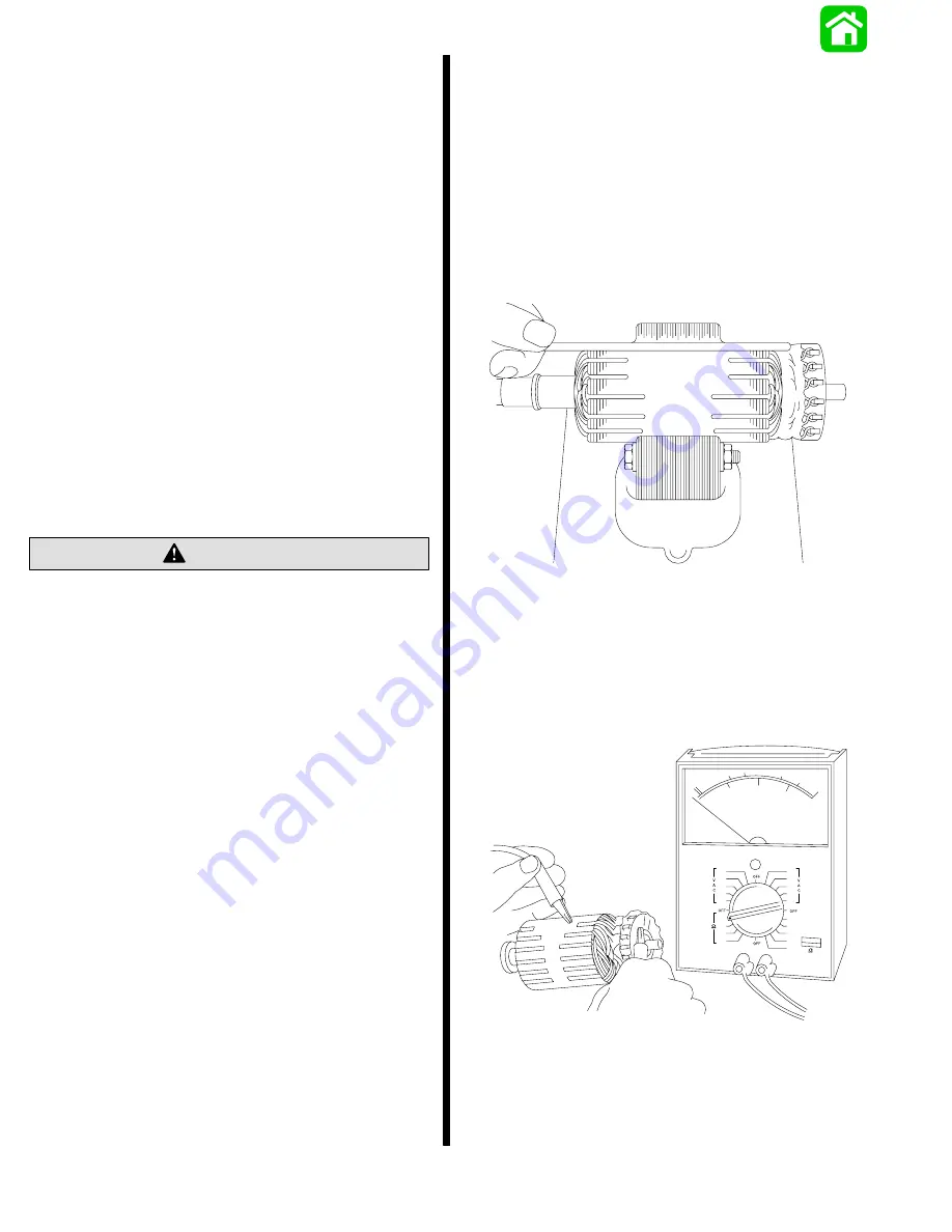
ARMATURE TEST FOR SHORTS
Check armature for short circuits by placing on
growler and holding hack saw blade over armature
core while armature is rotated. If saw blade vibrates,
armature is shorted. Recheck after cleaning between
commutator bars. If saw blade still vibrates, replace
armature.
11669
ARMATURE TEST FOR GROUND
1. Set ohmmeter to (R x 1 scale). Place one lead of
ohmmeter on armature core or shaft and other
lead on commutator.
2. If meter indicates continuity, armature is
grounded and must be replaced.
11675
Summary of Contents for 100
Page 4: ...GENERAL INFORMATION AND SPECIFICATIONS 1 ...
Page 18: ...IGNITION SYSTEM ELECTRICAL AND IGNITION A 2 ...
Page 30: ...11669 BATTERY CHARGING SYSTEM AND STARTING SYSTEM ELECTRICAL AND IGNITION B 2 ...
Page 58: ...22480 TIMING SYNCHRONIZING ADJUSTING ELECTRICAL AND IGNITION C 2 ...
Page 71: ...WIRING DIAGRAMS ELECTRICAL AND IGNITION D 2 ...
Page 86: ...FUEL SYSTEM AND CARBURETION A 3 ...
Page 118: ...OIL INJECTION SYSTEM B 3 ...
Page 127: ...20032 3 CYLINDER ENGINES POWERHEAD A 4 ...
Page 168: ...791 H GEAR HOUSING LOWER UNIT A 5 ...
Page 170: ...5A 1 90 13645 2 1095 LOWER UNIT Notes ...
Page 205: ...MID SECTION LOWER UNIT B 5 ...
Page 207: ...5B 1 90 13645 2 495 LOWER UNIT Notes ...
Page 218: ...SHOCK ABSORBER LOWER UNIT C 5 ...
Page 223: ...17250 DESIGN I SIDE FILL RESERVOIR POWER TRIM A 6 ...
Page 233: ...6A 9 POWER TRIM 90 13645 2 495 Commander Side Mount Remote Control Wiring Diagram ...
Page 268: ...DESIGN II AFT FILL RESERVOIR POWER TRIM B 6 51344 ...
Page 305: ...SINGLE RAM POWER TRIM C 6 51485 ...
Page 309: ...6C 3 90 13645 2 495 POWER TRIM Notes ...
Page 340: ...50099 ENGINE ATTACHMENTS ENGINE INSTALLATION 7 A ...
Page 369: ...TILLER HANDLE AND CO PILOT OUTBOARD MOTOR INSTALLATION ATTACHMENTS 7 B ...
Page 371: ...7B 1 90 13645 2 495 OUTBOARD MOTOR INSTALLATION ATTACHMENTS Notes ...