


3A-23
90-13645--2
495
FUEL SYSTEM AND CARBURETION
S
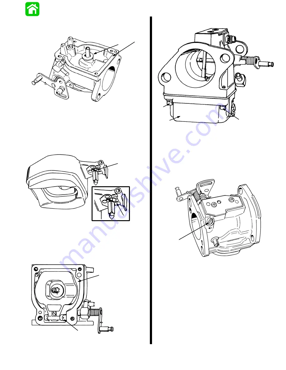
Install stem gasket.
S
Install fuel bowl gasket.
51119
a
b
a - Stem Gasket
b - Fuel Bowl Gasket
NOTE: If spring clip on inlet needle was removed, or
if needle was replaced, be sure spring clip is
reattached.
S
Attach spring clip on inlet needle to metal float tab
and place needle into its seat.
51115
a
b
a - Spring Clip
b - Float Tab
S
Install float into carburetor with float pin.
S
Adjust float following “Float Adjustment,” Page
3A-18.
51115
a
b
a - Float
b - Float Pin
S
Install float bowl.
51116
a
b
b
a - Float Bowl
b - Screw (4) Torque 18 lb. in. (2.1 N
m)
IDLE AIR SCREW
Idle air screw is preset by the manufacturer and is
NOT for field service. If the idle air screw should be-
come misadjusted, set air screw at 1/4 TURN OUT
from a LIGHTLY SEATED position.
51620
a
a - Idle Air Screw
Summary of Contents for 100
Page 4: ...GENERAL INFORMATION AND SPECIFICATIONS 1 ...
Page 18: ...IGNITION SYSTEM ELECTRICAL AND IGNITION A 2 ...
Page 30: ...11669 BATTERY CHARGING SYSTEM AND STARTING SYSTEM ELECTRICAL AND IGNITION B 2 ...
Page 58: ...22480 TIMING SYNCHRONIZING ADJUSTING ELECTRICAL AND IGNITION C 2 ...
Page 71: ...WIRING DIAGRAMS ELECTRICAL AND IGNITION D 2 ...
Page 86: ...FUEL SYSTEM AND CARBURETION A 3 ...
Page 118: ...OIL INJECTION SYSTEM B 3 ...
Page 127: ...20032 3 CYLINDER ENGINES POWERHEAD A 4 ...
Page 168: ...791 H GEAR HOUSING LOWER UNIT A 5 ...
Page 170: ...5A 1 90 13645 2 1095 LOWER UNIT Notes ...
Page 205: ...MID SECTION LOWER UNIT B 5 ...
Page 207: ...5B 1 90 13645 2 495 LOWER UNIT Notes ...
Page 218: ...SHOCK ABSORBER LOWER UNIT C 5 ...
Page 223: ...17250 DESIGN I SIDE FILL RESERVOIR POWER TRIM A 6 ...
Page 233: ...6A 9 POWER TRIM 90 13645 2 495 Commander Side Mount Remote Control Wiring Diagram ...
Page 268: ...DESIGN II AFT FILL RESERVOIR POWER TRIM B 6 51344 ...
Page 305: ...SINGLE RAM POWER TRIM C 6 51485 ...
Page 309: ...6C 3 90 13645 2 495 POWER TRIM Notes ...
Page 340: ...50099 ENGINE ATTACHMENTS ENGINE INSTALLATION 7 A ...
Page 369: ...TILLER HANDLE AND CO PILOT OUTBOARD MOTOR INSTALLATION ATTACHMENTS 7 B ...
Page 371: ...7B 1 90 13645 2 495 OUTBOARD MOTOR INSTALLATION ATTACHMENTS Notes ...