


5A-8
LOWER UNIT
90-13645--2
1095
Special Tools
Part No.
Description
91-46086A1
Puller Jaws
91-85716
Puller Bolt
91-34569A1
Slide Hammer
91-36569
Mandrel*
91-37263
Mandrel*
91-37323
Driver Rod*
91-56775
Drive Shaft Holding Tool
91-37241
Universal Puller Plate
91-83165M
Bearing Puller Assembly
91-31106
Mandrel
91-31108
Oil Seal Driver
91-37350
Mandrel
91-31229
Threaded Rod*
11-24156
Nut*
91-78473
Backlash Indicator Tool (3 Cyl)
91-58222A1
Dial Indicator
91-83155
Dial Indicator Adaptor Kit
91-12349A2
Pinion Gear Locating Tool
91-14308A1
Bearing Race Tool
91-14309A1
Bearing Installation Tool
91-14310A1
Wear Sleeve Installation Tool
91-14311A1
Bearing Preload Tool
91-13945
Bearing Installation Tool
91-13949
Oil Seal Driver
91-19660
Backlash Indicator Tool (4 Cyl)
*
From Bearing Removal and Installation Kit (91-31229A5)
Removal
WARNING
To prevent accidental engine starting, remove
(and isolate) spark plug leads from spark plugs
before removing gear housing.
1. Remove (and isolate) spark plug leads from spark
plugs.
2. Shift engine into forward gear.
3. Tilt engine to full “Up” position.
4. Remove 4 bolts (or locknuts on 1995 Models) and
washers (two each side).
5. Remove locknut and washer.
6. Remove gear housing.
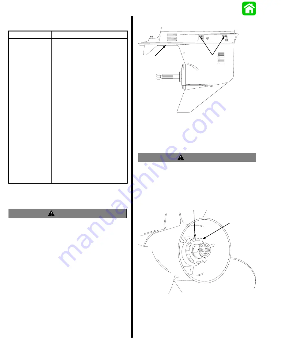
51552
b
a
a - Bolts (or Locknuts) and Washers
b - Locknut and Washer
Disassembly
Propeller Removal
WARNING
If gear housing is not removed from drive shaft
housing, before attempting to remove or install
the propeller, remove (and isolate) spark plug
leads from spark plugs to prevent engine from
starting accidentally.
1. Bend tabs of tab washer away from hub.
51871
a
b
a - Tab Washer
b - Hub
Summary of Contents for 100
Page 4: ...GENERAL INFORMATION AND SPECIFICATIONS 1 ...
Page 18: ...IGNITION SYSTEM ELECTRICAL AND IGNITION A 2 ...
Page 30: ...11669 BATTERY CHARGING SYSTEM AND STARTING SYSTEM ELECTRICAL AND IGNITION B 2 ...
Page 58: ...22480 TIMING SYNCHRONIZING ADJUSTING ELECTRICAL AND IGNITION C 2 ...
Page 71: ...WIRING DIAGRAMS ELECTRICAL AND IGNITION D 2 ...
Page 86: ...FUEL SYSTEM AND CARBURETION A 3 ...
Page 118: ...OIL INJECTION SYSTEM B 3 ...
Page 127: ...20032 3 CYLINDER ENGINES POWERHEAD A 4 ...
Page 168: ...791 H GEAR HOUSING LOWER UNIT A 5 ...
Page 170: ...5A 1 90 13645 2 1095 LOWER UNIT Notes ...
Page 205: ...MID SECTION LOWER UNIT B 5 ...
Page 207: ...5B 1 90 13645 2 495 LOWER UNIT Notes ...
Page 218: ...SHOCK ABSORBER LOWER UNIT C 5 ...
Page 223: ...17250 DESIGN I SIDE FILL RESERVOIR POWER TRIM A 6 ...
Page 233: ...6A 9 POWER TRIM 90 13645 2 495 Commander Side Mount Remote Control Wiring Diagram ...
Page 268: ...DESIGN II AFT FILL RESERVOIR POWER TRIM B 6 51344 ...
Page 305: ...SINGLE RAM POWER TRIM C 6 51485 ...
Page 309: ...6C 3 90 13645 2 495 POWER TRIM Notes ...
Page 340: ...50099 ENGINE ATTACHMENTS ENGINE INSTALLATION 7 A ...
Page 369: ...TILLER HANDLE AND CO PILOT OUTBOARD MOTOR INSTALLATION ATTACHMENTS 7 B ...
Page 371: ...7B 1 90 13645 2 495 OUTBOARD MOTOR INSTALLATION ATTACHMENTS Notes ...