


4A-31
90-13645--2
495
POWERHEAD
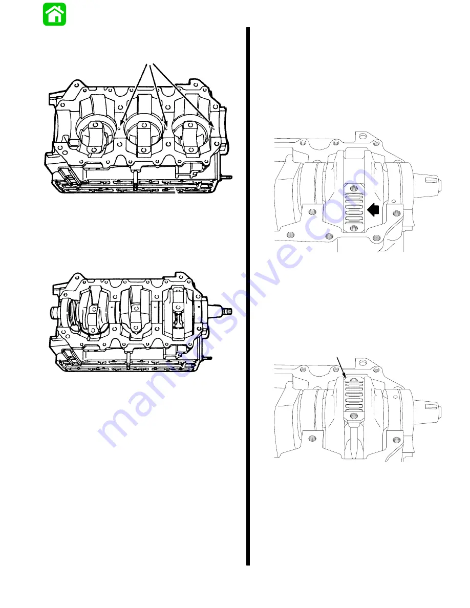
Position Cylinder Block and Piston Rods, as shown.
Note locating pins.
20038
LOWER (Gear)
END
FLYWHEEL
END (Top)
a
a - Locating Pins
Place crankshaft into cylinder block; align and seat
top and center main bearings so that locating pins on
block mate with holes in each bearing race.
20336
INSTALLING RODS TO CRANKSHAFT
Pull rod up to position shown.
Grease rod, bearing area, with Needle Bearing
Assembly Lubricant or 2-4-C w/Teflon - lay roller
bearings out on clean sheet of paper and grease
each bearing.
Place Bearing Cage in position.
Place Bearings in cage.
20045
Grease crankshaft journal with Needle Bearing As-
sembly Lubricant or 2-4-C w/Teflon.
Pull-up rod into contact with crankshaft journal.
Place Bearing Cage on crankcase journal.
Place Bearings into cage.
Align bearing cages with rod-to-cap mating surfaces.
20030
NOTE: Make sure that Rod Bolt Hole threads and
Rod Cap Bolt Hole threads are clean and oil free be-
fore reassembly.
Place Rod Cap carefully over cage and bearings,
and while holding cap tight to rod, and rod tight to
journal, insert bolt and lightly tighten, observing
cap-to-rod alignment. Install other bolt, rechecking
alignment.
Summary of Contents for 100
Page 4: ...GENERAL INFORMATION AND SPECIFICATIONS 1 ...
Page 18: ...IGNITION SYSTEM ELECTRICAL AND IGNITION A 2 ...
Page 30: ...11669 BATTERY CHARGING SYSTEM AND STARTING SYSTEM ELECTRICAL AND IGNITION B 2 ...
Page 58: ...22480 TIMING SYNCHRONIZING ADJUSTING ELECTRICAL AND IGNITION C 2 ...
Page 71: ...WIRING DIAGRAMS ELECTRICAL AND IGNITION D 2 ...
Page 86: ...FUEL SYSTEM AND CARBURETION A 3 ...
Page 118: ...OIL INJECTION SYSTEM B 3 ...
Page 127: ...20032 3 CYLINDER ENGINES POWERHEAD A 4 ...
Page 168: ...791 H GEAR HOUSING LOWER UNIT A 5 ...
Page 170: ...5A 1 90 13645 2 1095 LOWER UNIT Notes ...
Page 205: ...MID SECTION LOWER UNIT B 5 ...
Page 207: ...5B 1 90 13645 2 495 LOWER UNIT Notes ...
Page 218: ...SHOCK ABSORBER LOWER UNIT C 5 ...
Page 223: ...17250 DESIGN I SIDE FILL RESERVOIR POWER TRIM A 6 ...
Page 233: ...6A 9 POWER TRIM 90 13645 2 495 Commander Side Mount Remote Control Wiring Diagram ...
Page 268: ...DESIGN II AFT FILL RESERVOIR POWER TRIM B 6 51344 ...
Page 305: ...SINGLE RAM POWER TRIM C 6 51485 ...
Page 309: ...6C 3 90 13645 2 495 POWER TRIM Notes ...
Page 340: ...50099 ENGINE ATTACHMENTS ENGINE INSTALLATION 7 A ...
Page 369: ...TILLER HANDLE AND CO PILOT OUTBOARD MOTOR INSTALLATION ATTACHMENTS 7 B ...
Page 371: ...7B 1 90 13645 2 495 OUTBOARD MOTOR INSTALLATION ATTACHMENTS Notes ...