


4A-18
90-13645--2
495
POWERHEAD
CYLINDER BORE SIZE
Piston Size
Cylinder Block
Finish Hone
Standard Diameter
3.375 in.
(85.725mm)
.015 Oversize
3.390 in.
(86.106mm)
.030 Oversize
3.405 in.
(86.487mm)
S
Inspect cylinder bores for scoring (a transfer of
aluminum from piston to cylinder wall). Cylinder
wall scoring usually can be “cleaned up” by honing
or reboring.
When reboring cylinder block, remove hone
frequently and check condition of cylinder walls.
DO NOT hone any more than absolutely
necessary, as hone can remove cylinder wall
material rapidly.
CAUTION
HONING PROCEDURE
Follow hone manufacturer’s recommendations for
use of hone cleaning and lubrication during honing.
IMPORTANT: After honing, bores should be thor-
oughly cleaned with hot water and detergent.
Scrub well with stiff bristle brush and rinse with
hot water. If any abrasive material is allowed to re-
main in the cylinder bore, it will cause a rapid wear
of new piston rings and cylinder bore. After clean-
ing, bores should be swabbed several times with
2 cycle engine oil and a clean cloth. Wipe excess
oil with clean, dry cloth. Cylinders should not be
cleaned with kerosene or gasoline. Clean remain-
der of cylinder block.
S
Hone all cylinder walls just enough to de-glaze.
S
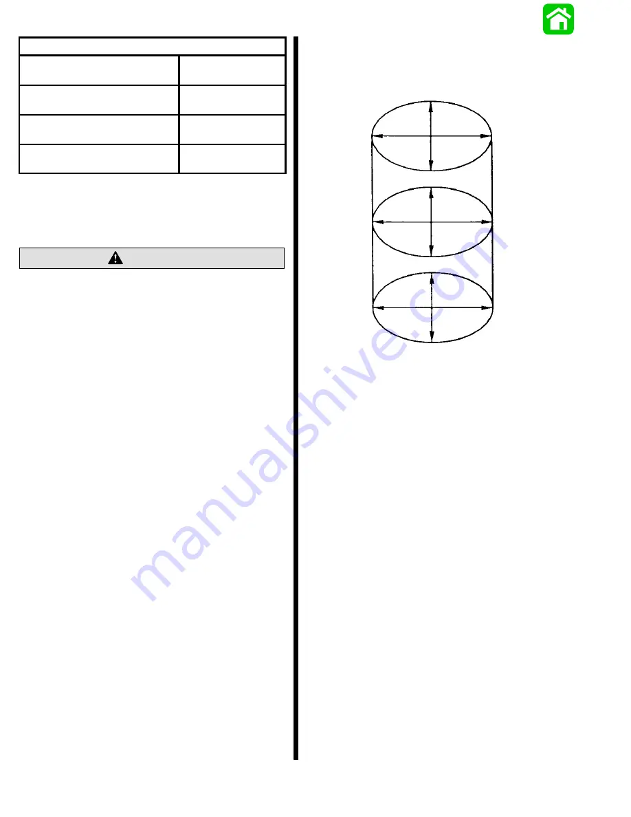
Measure cylinder bore inside diameter (with an in-
side micrometer) of each cylinder, as shown be-
low. Check for tapered, out-of-round (“egg-
shaped”) and oversize bore.
TOP
CENTER
BOTTOM
S
If a cylinder bore is tapered, out-of-round or worn
more than 0.003 in. (0.076mm) from standard
“Cylinder Block Finish Hone” diameter (refer to
chart), it will be necessary to rebore that cylinder(s)
to designated oversize bore and install oversize
piston(s) and piston rings during reassembly.
NOTE: The weight of an oversize piston is approxi-
mately the same as a standard size piston; therefore,
it is not necessary to rebore all cylinders in a block just
because one cylinder requires reboring.
IMPORTANT: Ports must be deburred after hon-
ing.
S
After honing and thoroughly cleaning cylinder
bores, apply 2 cycle outboard oil to cylinder walls
to prevent rusting.
Summary of Contents for 100
Page 4: ...GENERAL INFORMATION AND SPECIFICATIONS 1 ...
Page 18: ...IGNITION SYSTEM ELECTRICAL AND IGNITION A 2 ...
Page 30: ...11669 BATTERY CHARGING SYSTEM AND STARTING SYSTEM ELECTRICAL AND IGNITION B 2 ...
Page 58: ...22480 TIMING SYNCHRONIZING ADJUSTING ELECTRICAL AND IGNITION C 2 ...
Page 71: ...WIRING DIAGRAMS ELECTRICAL AND IGNITION D 2 ...
Page 86: ...FUEL SYSTEM AND CARBURETION A 3 ...
Page 118: ...OIL INJECTION SYSTEM B 3 ...
Page 127: ...20032 3 CYLINDER ENGINES POWERHEAD A 4 ...
Page 168: ...791 H GEAR HOUSING LOWER UNIT A 5 ...
Page 170: ...5A 1 90 13645 2 1095 LOWER UNIT Notes ...
Page 205: ...MID SECTION LOWER UNIT B 5 ...
Page 207: ...5B 1 90 13645 2 495 LOWER UNIT Notes ...
Page 218: ...SHOCK ABSORBER LOWER UNIT C 5 ...
Page 223: ...17250 DESIGN I SIDE FILL RESERVOIR POWER TRIM A 6 ...
Page 233: ...6A 9 POWER TRIM 90 13645 2 495 Commander Side Mount Remote Control Wiring Diagram ...
Page 268: ...DESIGN II AFT FILL RESERVOIR POWER TRIM B 6 51344 ...
Page 305: ...SINGLE RAM POWER TRIM C 6 51485 ...
Page 309: ...6C 3 90 13645 2 495 POWER TRIM Notes ...
Page 340: ...50099 ENGINE ATTACHMENTS ENGINE INSTALLATION 7 A ...
Page 369: ...TILLER HANDLE AND CO PILOT OUTBOARD MOTOR INSTALLATION ATTACHMENTS 7 B ...
Page 371: ...7B 1 90 13645 2 495 OUTBOARD MOTOR INSTALLATION ATTACHMENTS Notes ...