


6B-30
90-13645--2
495
POWER TRIM
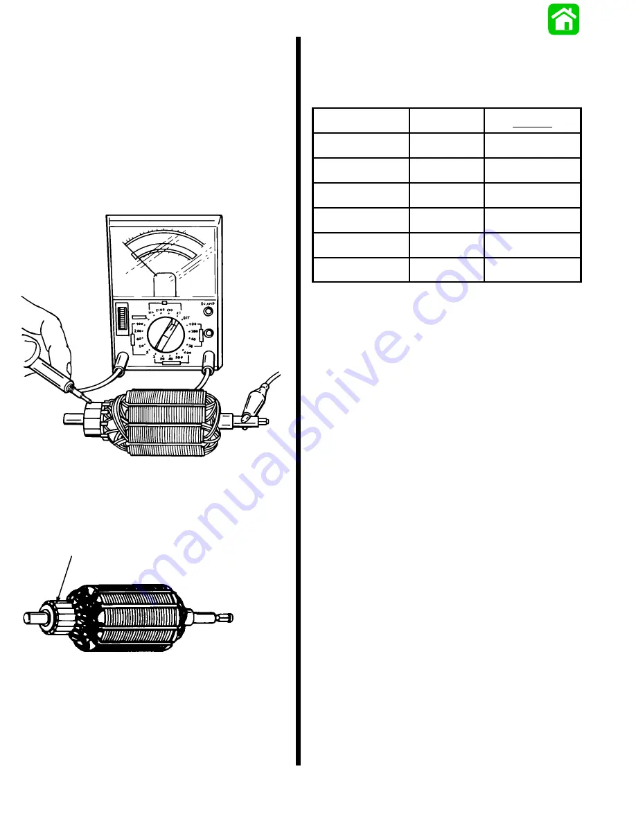
Armature Tests
TEST FOR SHORTS
Check armature on a Growler per the Growler man-
ufacturer’s instructions. Replace armature if a short is
indicated.
TEST FOR GROUND
1. Use an Ohmmeter (R x 1 scale). Connect one
lead on armature shaft and other lead on commu-
tator. If continuity is indicated, armature is
grounded. Replace armature.
51359
CHECKING AND CLEANING COMMUTATOR
1. If commutator is worn it may be turned on an
armature conditioner or a lathe.
2. Clean commutator with “00” sandpaper.
a
a - Commutator
FIELD TESTS
IMPORTANT: Commutator end of armature must
be installed in brushes when performing the fol-
lowing tests.
Ohmmeter
Leads Between
Resistance
(Ohms)
Scale Reading*
(x )
Green and Blue Motor
Wires
0
Full Continuity
(R x 1)
Green and Black Motor
Wires
0
Full Continuity
(R x 1)
Blue and Black Motor
Wires
0
Full Continuity
(R x 1)
Black Motor Wire, and
Frame (Motor Housing)
No
Continuity
Full Continuity
(R x 1)
Green Motor Wire, and
Frame
No
Continuity
Full Continuity
(R x 1)
Blue Motor Wire, and
Frame
No
Continuity
Full Continuity
(R x 1)
* If specified readings are not obtained, check for:
defective armature
dirty or worn brushes
dirty or worn commutator
If defective components are found, repair or replace
component(s) and retest.
Summary of Contents for 100
Page 4: ...GENERAL INFORMATION AND SPECIFICATIONS 1 ...
Page 18: ...IGNITION SYSTEM ELECTRICAL AND IGNITION A 2 ...
Page 30: ...11669 BATTERY CHARGING SYSTEM AND STARTING SYSTEM ELECTRICAL AND IGNITION B 2 ...
Page 58: ...22480 TIMING SYNCHRONIZING ADJUSTING ELECTRICAL AND IGNITION C 2 ...
Page 71: ...WIRING DIAGRAMS ELECTRICAL AND IGNITION D 2 ...
Page 86: ...FUEL SYSTEM AND CARBURETION A 3 ...
Page 118: ...OIL INJECTION SYSTEM B 3 ...
Page 127: ...20032 3 CYLINDER ENGINES POWERHEAD A 4 ...
Page 168: ...791 H GEAR HOUSING LOWER UNIT A 5 ...
Page 170: ...5A 1 90 13645 2 1095 LOWER UNIT Notes ...
Page 205: ...MID SECTION LOWER UNIT B 5 ...
Page 207: ...5B 1 90 13645 2 495 LOWER UNIT Notes ...
Page 218: ...SHOCK ABSORBER LOWER UNIT C 5 ...
Page 223: ...17250 DESIGN I SIDE FILL RESERVOIR POWER TRIM A 6 ...
Page 233: ...6A 9 POWER TRIM 90 13645 2 495 Commander Side Mount Remote Control Wiring Diagram ...
Page 268: ...DESIGN II AFT FILL RESERVOIR POWER TRIM B 6 51344 ...
Page 305: ...SINGLE RAM POWER TRIM C 6 51485 ...
Page 309: ...6C 3 90 13645 2 495 POWER TRIM Notes ...
Page 340: ...50099 ENGINE ATTACHMENTS ENGINE INSTALLATION 7 A ...
Page 369: ...TILLER HANDLE AND CO PILOT OUTBOARD MOTOR INSTALLATION ATTACHMENTS 7 B ...
Page 371: ...7B 1 90 13645 2 495 OUTBOARD MOTOR INSTALLATION ATTACHMENTS Notes ...