


6A-16
POWER TRIM
90-13645--2
495
No Voltage Indicated:
Check that voltage is being supplied to
control by performing the following checks:
D
DO NOT start engine.
D
Turn ignition switch to “Run” position.
D
Check for voltage at any instrument, us-
ing a Voltmeter.
* Remote Control NOT Equipped with Trailer Button
No Voltage Indicated:
D
Check battery leads and RED leads
(between engine starter motor sole-
noid and Point 3) for poor connections
or open circuits.
D
Check battery charge.
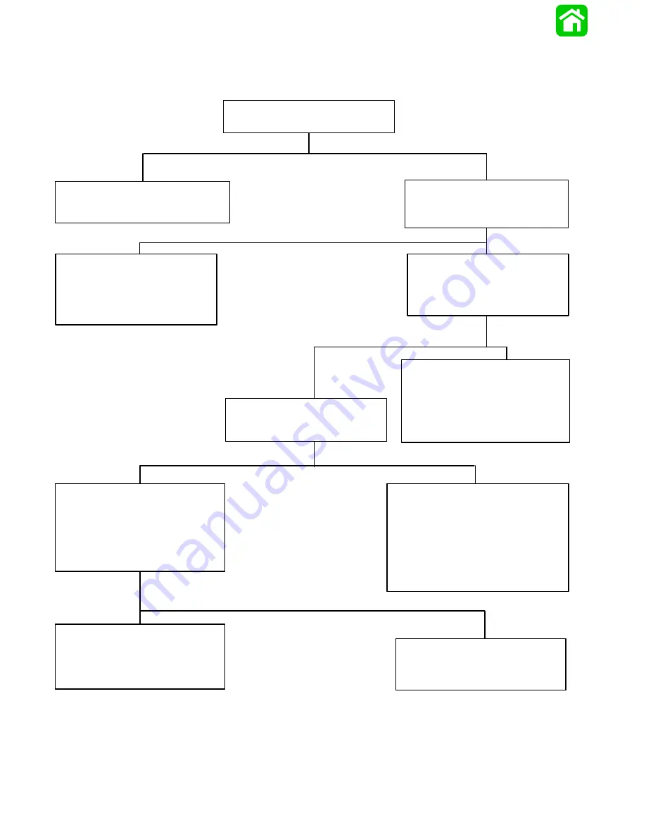
Troubleshooting the “Down” and “Up” Circuits*
(All Circuits Inoperative)
Check two in-line fuses (under cowl) to see
if fuses are blown.
Fuses Not Blown:
Connect Voltmeter red lead to Point 3,
and black lead to ground. Battery voltage
should be indicated.
Battery Voltage Indicated:
D
Connect Voltmeter RED lead to Point
10 and black lead to ground.
D
Depress “Up” trim button and check for
battery voltage.
Battery Voltage Indicated:
D
Check BLACK ground wires at solenoids
for poor connection or poor ground.
D
Check BLACK motor lead for poor ground
at Point 12. If wire is grounded, the pump
motor is faulty. Refer to “Motor and Elec-
trical Tests/Repair,” following.
No Voltage Indicated:
Red wire is open between Point 14 and RED
terminal on back of the ignition switch.
D
Check for loose or corroded connections.
D
Check for open in wire.
Battery Voltage Indicated:
There is an open circuit in wire between
Point 5 and RED terminal on the back of the
ignition switch.
No Voltage Indicated:
Connect RED Voltmeter lead to Point 5,
and BLACK lead to ground.
Battery Voltage Indicated:
Trim switch is faulty or there is an open circuit
in wires [GREEN-WHITE, BLUE-WHITE and
PURPLE-WHITE (or PURPLE)] between trim
buttons and trim pump.
D
Check trim switch.
D
Check all trim harness connectors for loose
or corroded connections.
D
Check for pinched or severed wires.
Blown Fuse:
D
Correct problem that caused fuse to blow.
D
Replace fuse.
Summary of Contents for 100
Page 4: ...GENERAL INFORMATION AND SPECIFICATIONS 1 ...
Page 18: ...IGNITION SYSTEM ELECTRICAL AND IGNITION A 2 ...
Page 30: ...11669 BATTERY CHARGING SYSTEM AND STARTING SYSTEM ELECTRICAL AND IGNITION B 2 ...
Page 58: ...22480 TIMING SYNCHRONIZING ADJUSTING ELECTRICAL AND IGNITION C 2 ...
Page 71: ...WIRING DIAGRAMS ELECTRICAL AND IGNITION D 2 ...
Page 86: ...FUEL SYSTEM AND CARBURETION A 3 ...
Page 118: ...OIL INJECTION SYSTEM B 3 ...
Page 127: ...20032 3 CYLINDER ENGINES POWERHEAD A 4 ...
Page 168: ...791 H GEAR HOUSING LOWER UNIT A 5 ...
Page 170: ...5A 1 90 13645 2 1095 LOWER UNIT Notes ...
Page 205: ...MID SECTION LOWER UNIT B 5 ...
Page 207: ...5B 1 90 13645 2 495 LOWER UNIT Notes ...
Page 218: ...SHOCK ABSORBER LOWER UNIT C 5 ...
Page 223: ...17250 DESIGN I SIDE FILL RESERVOIR POWER TRIM A 6 ...
Page 233: ...6A 9 POWER TRIM 90 13645 2 495 Commander Side Mount Remote Control Wiring Diagram ...
Page 268: ...DESIGN II AFT FILL RESERVOIR POWER TRIM B 6 51344 ...
Page 305: ...SINGLE RAM POWER TRIM C 6 51485 ...
Page 309: ...6C 3 90 13645 2 495 POWER TRIM Notes ...
Page 340: ...50099 ENGINE ATTACHMENTS ENGINE INSTALLATION 7 A ...
Page 369: ...TILLER HANDLE AND CO PILOT OUTBOARD MOTOR INSTALLATION ATTACHMENTS 7 B ...
Page 371: ...7B 1 90 13645 2 495 OUTBOARD MOTOR INSTALLATION ATTACHMENTS Notes ...