


3B-1
90-13645--2
1095
OIL INJECTION SYSTEM
Description
Be careful not to get dirt or other contamination in
tank, hoses or other components of the oil
injection system.
CAUTION
Engines with oil injection must be run on a fuel/oil
ratio of 50:1 in the fuel tank, in addition to the oil
supplied by the oil injection system, for the first 30
gallons of fuel. Refer to break-in procedure in the
Operation and Maintenance Manual.
CAUTION
If an electric fuel pump is to be used on engines
with oil injection, the fuel pressure at the engine
must not exceed 6 psig. If necessary, install a
pressure regulator between electric fuel pump
and engine and set at 6 psig maximum.
CAUTION
The major components of the oil injection system are
an oil tank, oil pump, and low oil warning system.
The oil tank is attached to the powerhead and holds
oil for delivery to the oil pump.
Oil is gravity fed to the oil pump via a hose.
The oil pump injects oil into the fuel at the fuel pump,
and is driven by the crankshaft.
A link rod is connected between the throttle linkage
and oil pump lever. When the throttle position is
changed, the link rod rotates the oil pump valve,
which changes the fuel/oil ratio from approximately
80:1 at idle speed, to 50:1 at wide-open-throttle.
The oil tank is equipped with a low oil sensor and a
magnetic float. When oil level in oil tank drops to
approximately 1 quart (.95 liter), the magnetized float
will complete the circuit between the low oil sensor
leads, causing the warning horn to sound.
IMPORTANT: Warning horn is also connected to
the powerhead temperature sensor. If the warning
horn sounds, either the oil level in oil tank is low,
or the powerhead is overheated.
A warning horn test button is located next to oil tank
fill cap. When ignition switch is in the “Run” position
and warning horn test button is depressed, the horn
should sound.
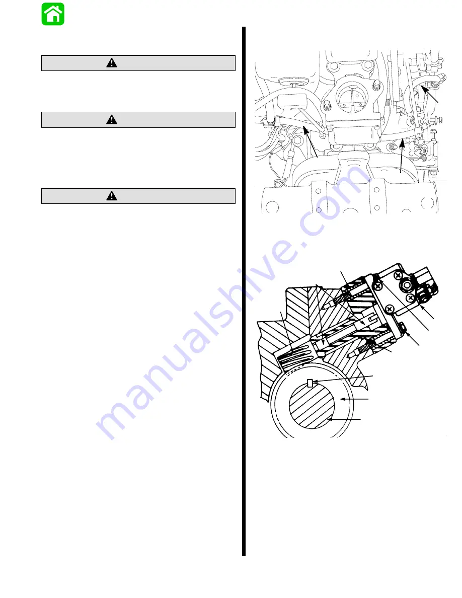
Hose Connections
22511
a
a
a
a - Oil Hose Connections
Oil Pump Drive System
a
b
c
d
e
f
g
h
i
i
a - Crankshaft
b - Drive Key
c - Drive Gear
d - Apply Quicksilver 2-4-C w/Teflon on Both Areas
e - Driven Gear
f - O-Rings [.739
(18.77mm) I.D. x .809
(20.55mm) O.D.]
g - Spacer
h - Oil Pump
i - Bolts; Torque to 60 lb. in. (6.8 N.m)
Summary of Contents for 100
Page 4: ...GENERAL INFORMATION AND SPECIFICATIONS 1 ...
Page 18: ...IGNITION SYSTEM ELECTRICAL AND IGNITION A 2 ...
Page 30: ...11669 BATTERY CHARGING SYSTEM AND STARTING SYSTEM ELECTRICAL AND IGNITION B 2 ...
Page 58: ...22480 TIMING SYNCHRONIZING ADJUSTING ELECTRICAL AND IGNITION C 2 ...
Page 71: ...WIRING DIAGRAMS ELECTRICAL AND IGNITION D 2 ...
Page 86: ...FUEL SYSTEM AND CARBURETION A 3 ...
Page 118: ...OIL INJECTION SYSTEM B 3 ...
Page 127: ...20032 3 CYLINDER ENGINES POWERHEAD A 4 ...
Page 168: ...791 H GEAR HOUSING LOWER UNIT A 5 ...
Page 170: ...5A 1 90 13645 2 1095 LOWER UNIT Notes ...
Page 205: ...MID SECTION LOWER UNIT B 5 ...
Page 207: ...5B 1 90 13645 2 495 LOWER UNIT Notes ...
Page 218: ...SHOCK ABSORBER LOWER UNIT C 5 ...
Page 223: ...17250 DESIGN I SIDE FILL RESERVOIR POWER TRIM A 6 ...
Page 233: ...6A 9 POWER TRIM 90 13645 2 495 Commander Side Mount Remote Control Wiring Diagram ...
Page 268: ...DESIGN II AFT FILL RESERVOIR POWER TRIM B 6 51344 ...
Page 305: ...SINGLE RAM POWER TRIM C 6 51485 ...
Page 309: ...6C 3 90 13645 2 495 POWER TRIM Notes ...
Page 340: ...50099 ENGINE ATTACHMENTS ENGINE INSTALLATION 7 A ...
Page 369: ...TILLER HANDLE AND CO PILOT OUTBOARD MOTOR INSTALLATION ATTACHMENTS 7 B ...
Page 371: ...7B 1 90 13645 2 495 OUTBOARD MOTOR INSTALLATION ATTACHMENTS Notes ...