


7A-10
ENGINE ATTACHMENTS
90-13645--2
495
b
d
c
b
a
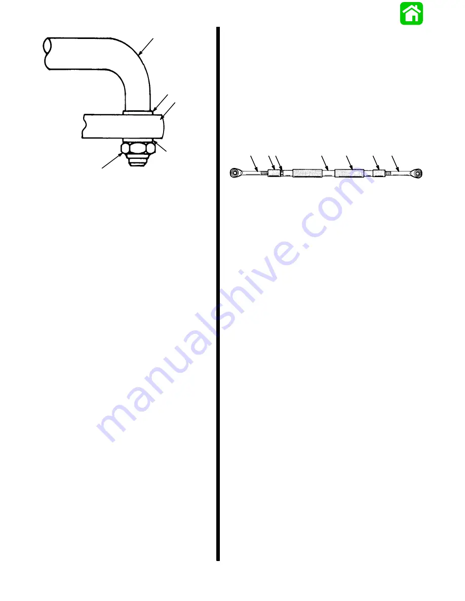
a - Steering Link Rod
b - Flat Washer (5/8
″
O.D.)
c - Steering Cable End
d - Locknut; Tighten Until it Seats [DO NOT Exceed 120 lbs. in.
(13.5 N
m)], then Back Nut Off 1/4-Turn.
Figure 7. Steering Link Rod Assembled on
Steering Cable
7. Lubricate hole(s) in end of steering cable(s) with
Multi-purpose Lubricant and assemble steering
link rod(s) to steering cable end, as shown in Fig-
ure 7. Tighten self-locking nut until it seats [DO
NOT exceed 120 lbs. in. (13.5 N
m)], then back
nut off 1/4-turn.
Steering Eyes and Coupler Installation
1. Position engines so that they are facing straight
forward. (Distance between centers of threaded
pivot bolt holes in engine steering arms must be
equal to distance between propeller shaft
centers.)
2. Lubricate inside of rubber sleeves (Figure 8) and
slide onto coupler.
3. Slide rubber bushings (Figure 8) onto steering
eyes.
50061
a
b
c
d
e
a
e
a - Rubber Bushing
b - Rubber Sleeve
c - Jam Nut; Torque to 20 lbs. ft. (13.5 N·m)
d - Coupler
e - Steering Eye
Figure 8. Coupler Assembled
Summary of Contents for 100
Page 4: ...GENERAL INFORMATION AND SPECIFICATIONS 1 ...
Page 18: ...IGNITION SYSTEM ELECTRICAL AND IGNITION A 2 ...
Page 30: ...11669 BATTERY CHARGING SYSTEM AND STARTING SYSTEM ELECTRICAL AND IGNITION B 2 ...
Page 58: ...22480 TIMING SYNCHRONIZING ADJUSTING ELECTRICAL AND IGNITION C 2 ...
Page 71: ...WIRING DIAGRAMS ELECTRICAL AND IGNITION D 2 ...
Page 86: ...FUEL SYSTEM AND CARBURETION A 3 ...
Page 118: ...OIL INJECTION SYSTEM B 3 ...
Page 127: ...20032 3 CYLINDER ENGINES POWERHEAD A 4 ...
Page 168: ...791 H GEAR HOUSING LOWER UNIT A 5 ...
Page 170: ...5A 1 90 13645 2 1095 LOWER UNIT Notes ...
Page 205: ...MID SECTION LOWER UNIT B 5 ...
Page 207: ...5B 1 90 13645 2 495 LOWER UNIT Notes ...
Page 218: ...SHOCK ABSORBER LOWER UNIT C 5 ...
Page 223: ...17250 DESIGN I SIDE FILL RESERVOIR POWER TRIM A 6 ...
Page 233: ...6A 9 POWER TRIM 90 13645 2 495 Commander Side Mount Remote Control Wiring Diagram ...
Page 268: ...DESIGN II AFT FILL RESERVOIR POWER TRIM B 6 51344 ...
Page 305: ...SINGLE RAM POWER TRIM C 6 51485 ...
Page 309: ...6C 3 90 13645 2 495 POWER TRIM Notes ...
Page 340: ...50099 ENGINE ATTACHMENTS ENGINE INSTALLATION 7 A ...
Page 369: ...TILLER HANDLE AND CO PILOT OUTBOARD MOTOR INSTALLATION ATTACHMENTS 7 B ...
Page 371: ...7B 1 90 13645 2 495 OUTBOARD MOTOR INSTALLATION ATTACHMENTS Notes ...