


6C-31
90-13645--2
495
POWER-TRIM
Purging Power Trim Unit
Manual release valve must be in full closed posi-
tion during power trim purging and operation.
1. Secure power trim unit in soft jawed vise.
2. Remove fill cap. Add Quicksilver Power Trim and
Steering Fluid (92-90100A12) or Automatic
Transmission Fluid (ATF) Type F, FA or Dexron II
up to threads of reservoir. Install cap.
51432
a
a - Fill Cap
3. Using a 12 volt power supply connect POSITIVE
lead to GREEN wire, NEGATIVE lead to BLUE
wire and drive trim rod to the DOWN position.
Connect POSITIVE lead to BLUE wire and NEG-
ATIVE lead to GREEN wire and drive trim rod to
the UP position. Recheck fluid level, add fluid as
required and repeat cycle until fluid level remains
at lower portion of threads.
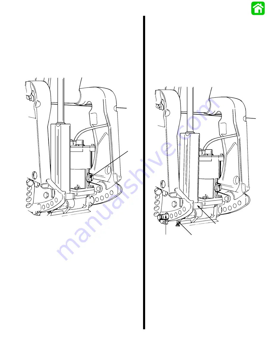
Power Trim Unit Installation
1. Apply 2-4-C w/Teflon (92-825407A12) to lower
pivot pin bore and pivot pin surface.
2. Position trim cylinder assembly (BOTTOM
FIRST) between clamp brackets and route trim
pump electrical harness through access hole in
starboard clamp bracket.
3. Start lower pivot pin into pivot pin bore and posi-
tion lower cross pin (RETAINED) in its respective
hole.
51515
a
b
c
a - Trim Cylinder Assembly
b - Lower Pivot Pin
c - Lower Cross Pin
Summary of Contents for 100
Page 4: ...GENERAL INFORMATION AND SPECIFICATIONS 1 ...
Page 18: ...IGNITION SYSTEM ELECTRICAL AND IGNITION A 2 ...
Page 30: ...11669 BATTERY CHARGING SYSTEM AND STARTING SYSTEM ELECTRICAL AND IGNITION B 2 ...
Page 58: ...22480 TIMING SYNCHRONIZING ADJUSTING ELECTRICAL AND IGNITION C 2 ...
Page 71: ...WIRING DIAGRAMS ELECTRICAL AND IGNITION D 2 ...
Page 86: ...FUEL SYSTEM AND CARBURETION A 3 ...
Page 118: ...OIL INJECTION SYSTEM B 3 ...
Page 127: ...20032 3 CYLINDER ENGINES POWERHEAD A 4 ...
Page 168: ...791 H GEAR HOUSING LOWER UNIT A 5 ...
Page 170: ...5A 1 90 13645 2 1095 LOWER UNIT Notes ...
Page 205: ...MID SECTION LOWER UNIT B 5 ...
Page 207: ...5B 1 90 13645 2 495 LOWER UNIT Notes ...
Page 218: ...SHOCK ABSORBER LOWER UNIT C 5 ...
Page 223: ...17250 DESIGN I SIDE FILL RESERVOIR POWER TRIM A 6 ...
Page 233: ...6A 9 POWER TRIM 90 13645 2 495 Commander Side Mount Remote Control Wiring Diagram ...
Page 268: ...DESIGN II AFT FILL RESERVOIR POWER TRIM B 6 51344 ...
Page 305: ...SINGLE RAM POWER TRIM C 6 51485 ...
Page 309: ...6C 3 90 13645 2 495 POWER TRIM Notes ...
Page 340: ...50099 ENGINE ATTACHMENTS ENGINE INSTALLATION 7 A ...
Page 369: ...TILLER HANDLE AND CO PILOT OUTBOARD MOTOR INSTALLATION ATTACHMENTS 7 B ...
Page 371: ...7B 1 90 13645 2 495 OUTBOARD MOTOR INSTALLATION ATTACHMENTS Notes ...