


5A-16
LOWER UNIT
90-13645--2
1095
8. Replace drive shaft if splines are worn or twisted.
9. If bearing surface is damaged, replace drive shaft
and corresponding bearing.
IMPORTANT: Do not tighten vise against drive
shaft.
10. If wear sleeve is deeply grooved allowing water to
enter gear case, remove (and discard) sleeve us-
ing Universal Puller Plate (91-37241) and lead
hammer.
19710
a
b
c
d
a
e
a - Splines
b - Bearing Surface
c - Wear Sleeve
d - Universal Puller Plate (91-37241)
e - Lead Hammer
11. Remove (and discard) rubber ring.
19152
a
a - Rubber Ring
Upper Drive Shaft Bearing
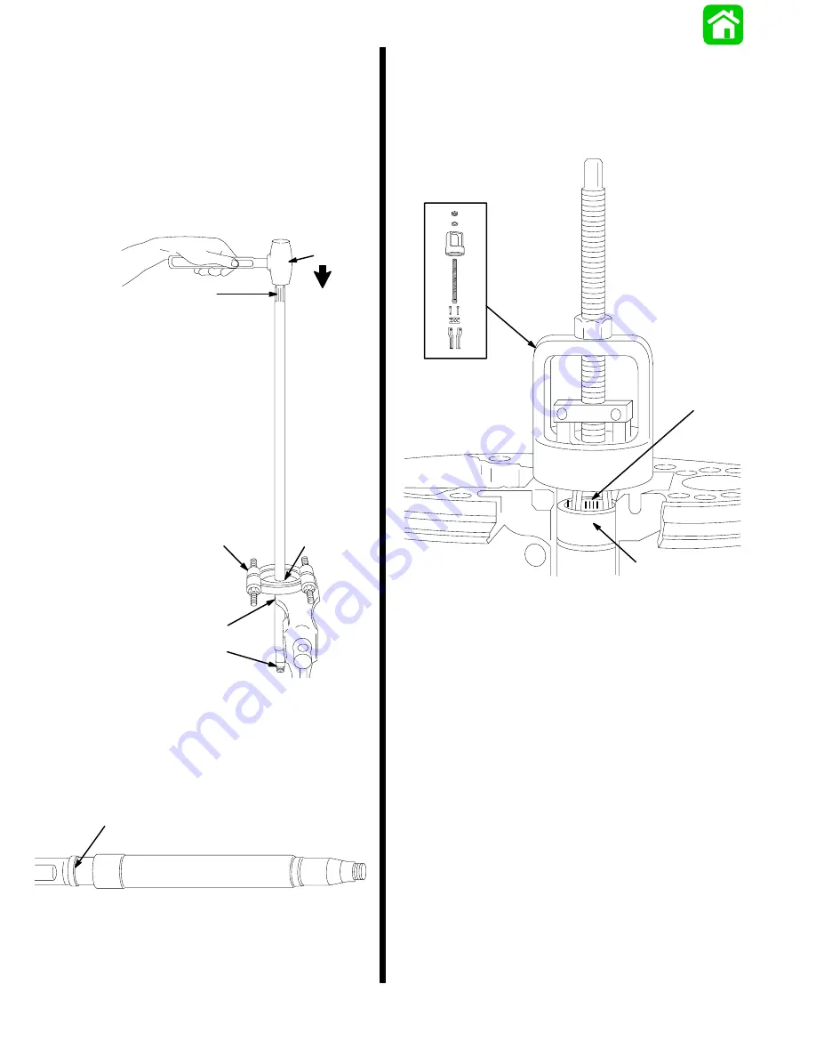
1. Replace upper drive shaft bearing and sleeve if
either are rust stained, or if bearing will not roll
freely. Remove bearing and then sleeve using
Puller Assembly (91-83165M) with suitable jaws.
19177
a
b
c
a - Upper Drive Shaft Bearing
b - Sleeve
c - Puller Assembly (91-83165M)
Summary of Contents for 100
Page 4: ...GENERAL INFORMATION AND SPECIFICATIONS 1 ...
Page 18: ...IGNITION SYSTEM ELECTRICAL AND IGNITION A 2 ...
Page 30: ...11669 BATTERY CHARGING SYSTEM AND STARTING SYSTEM ELECTRICAL AND IGNITION B 2 ...
Page 58: ...22480 TIMING SYNCHRONIZING ADJUSTING ELECTRICAL AND IGNITION C 2 ...
Page 71: ...WIRING DIAGRAMS ELECTRICAL AND IGNITION D 2 ...
Page 86: ...FUEL SYSTEM AND CARBURETION A 3 ...
Page 118: ...OIL INJECTION SYSTEM B 3 ...
Page 127: ...20032 3 CYLINDER ENGINES POWERHEAD A 4 ...
Page 168: ...791 H GEAR HOUSING LOWER UNIT A 5 ...
Page 170: ...5A 1 90 13645 2 1095 LOWER UNIT Notes ...
Page 205: ...MID SECTION LOWER UNIT B 5 ...
Page 207: ...5B 1 90 13645 2 495 LOWER UNIT Notes ...
Page 218: ...SHOCK ABSORBER LOWER UNIT C 5 ...
Page 223: ...17250 DESIGN I SIDE FILL RESERVOIR POWER TRIM A 6 ...
Page 233: ...6A 9 POWER TRIM 90 13645 2 495 Commander Side Mount Remote Control Wiring Diagram ...
Page 268: ...DESIGN II AFT FILL RESERVOIR POWER TRIM B 6 51344 ...
Page 305: ...SINGLE RAM POWER TRIM C 6 51485 ...
Page 309: ...6C 3 90 13645 2 495 POWER TRIM Notes ...
Page 340: ...50099 ENGINE ATTACHMENTS ENGINE INSTALLATION 7 A ...
Page 369: ...TILLER HANDLE AND CO PILOT OUTBOARD MOTOR INSTALLATION ATTACHMENTS 7 B ...
Page 371: ...7B 1 90 13645 2 495 OUTBOARD MOTOR INSTALLATION ATTACHMENTS Notes ...