


5A-14
LOWER UNIT
90-13645--2
1095
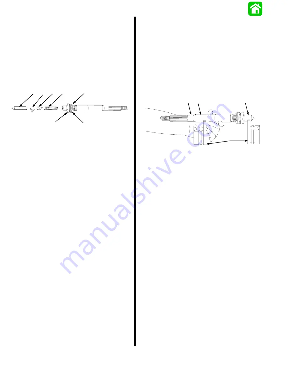
13. Remove components from propeller shaft.
14. Replace cam follower if worn or pitted.
15. Replace sliding clutch if jaws are rounded or
chipped. Rounded jaws indicate one or more of
the following:
a. Improper shift cable adjustment.
b. Engine idle speed too high while shifting.
c. Shifting from neutral to reverse (or forward) too
slowly.
51265
a
b
c
d
e
f
f
a - Cam Follower
b - 3 Metal Balls
c - Guide Block
d - Spring
e - Sliding Clutch
f - Jaws
16. Check bearing surfaces of propeller shaft for pit-
ting or wear. If shaft is worn or pitted, replace shaft
and corresponding bearing.
17. Replace propeller shaft if any of the following
exist:
a. Splines are twisted or worn.
b. Oil seal surface is grooved.
c. Shaft has a noticeable “wobble” or is bent more
than 0.009 in. (0.228mm). Prop shaft trueness
should be measured with a dial indicator with
prop shaft on V-blocks.
51877
c
b
a
b
a - V-Blocks
b - Bearing Surfaces
c - Measure with Dial Indicator at this Point.
Summary of Contents for 100
Page 4: ...GENERAL INFORMATION AND SPECIFICATIONS 1 ...
Page 18: ...IGNITION SYSTEM ELECTRICAL AND IGNITION A 2 ...
Page 30: ...11669 BATTERY CHARGING SYSTEM AND STARTING SYSTEM ELECTRICAL AND IGNITION B 2 ...
Page 58: ...22480 TIMING SYNCHRONIZING ADJUSTING ELECTRICAL AND IGNITION C 2 ...
Page 71: ...WIRING DIAGRAMS ELECTRICAL AND IGNITION D 2 ...
Page 86: ...FUEL SYSTEM AND CARBURETION A 3 ...
Page 118: ...OIL INJECTION SYSTEM B 3 ...
Page 127: ...20032 3 CYLINDER ENGINES POWERHEAD A 4 ...
Page 168: ...791 H GEAR HOUSING LOWER UNIT A 5 ...
Page 170: ...5A 1 90 13645 2 1095 LOWER UNIT Notes ...
Page 205: ...MID SECTION LOWER UNIT B 5 ...
Page 207: ...5B 1 90 13645 2 495 LOWER UNIT Notes ...
Page 218: ...SHOCK ABSORBER LOWER UNIT C 5 ...
Page 223: ...17250 DESIGN I SIDE FILL RESERVOIR POWER TRIM A 6 ...
Page 233: ...6A 9 POWER TRIM 90 13645 2 495 Commander Side Mount Remote Control Wiring Diagram ...
Page 268: ...DESIGN II AFT FILL RESERVOIR POWER TRIM B 6 51344 ...
Page 305: ...SINGLE RAM POWER TRIM C 6 51485 ...
Page 309: ...6C 3 90 13645 2 495 POWER TRIM Notes ...
Page 340: ...50099 ENGINE ATTACHMENTS ENGINE INSTALLATION 7 A ...
Page 369: ...TILLER HANDLE AND CO PILOT OUTBOARD MOTOR INSTALLATION ATTACHMENTS 7 B ...
Page 371: ...7B 1 90 13645 2 495 OUTBOARD MOTOR INSTALLATION ATTACHMENTS Notes ...