


7A-9
ENGINE ATTACHMENTS
90-13645--2
495
c. Insert ends of steering cables thru engine tilt
tube and cable mounting tube (Figure 3).
Thread steering cable attaching nuts hand-tight
onto tubes.
e
50101
a
b
c
d
e
a
b
c
d
f
f
a - Flat Washer (2 Each Link Rod)
b - Nylon Insert Locknut - Torque Until it Seats [DO NOT Exceed
120 lb. in. (13.5 N
m) of Torque], then Back Off 1/4-Turn
c - Special Washer Head Bolt (10-14000) - Torque to 20 lb. ft.
(27.1 N
m)
d - Nylon Insert Locknut - Torque to 20 lb. ft. (27.1 N
m)
e - Steering Link Rod
f - Steering Cable End
Figure 3. Steering Cables and Link Rod Installed
NOTE: Torque steering cables’ attaching nuts and
install locking sleeves after final tension adjustment.
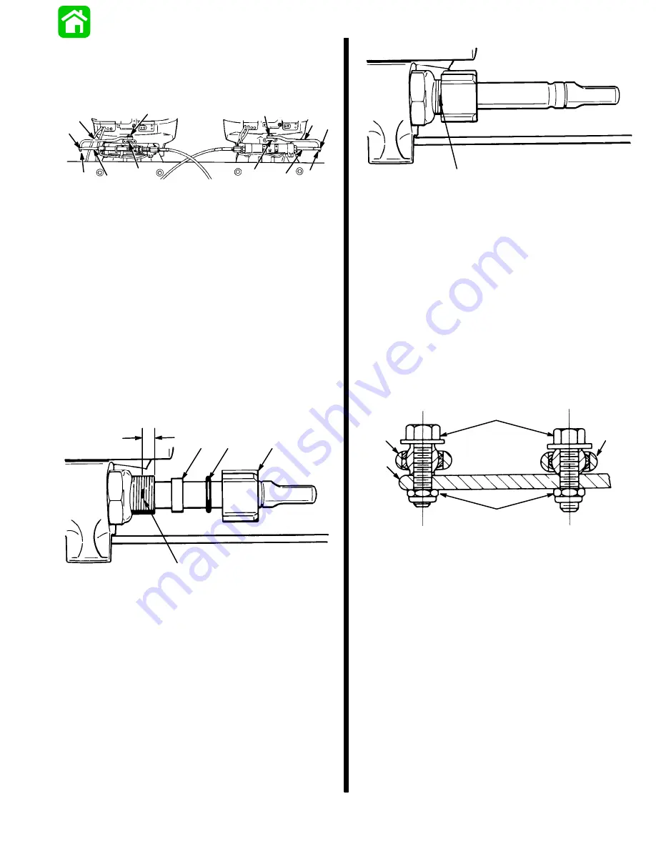
5. Install steering cable seal to steering cable
mounting tube, as follows:
a. Place a mark on steering cable mounting tube
5/8
″
(16mm) from end of tube (Figure 4).
50180
a
b
c
d
e
a - 5/8
″
from End of Tube
b - Place Mark on Tube Here.
c - Nylon Spacer
d - O-ring
e - Cap
Figure 4. Seal Installation Sequence
50180
a
a - Mark Made in Step 5a
Figure 5. Steering Cable Seal Installed
b. Slide plastic spacer, O-ring and cap (from kit)
over steering cable (Figure 4).
c. Thread cap onto steering cable mounting tube
up to mark (made on tube in Step “a” (Figure 5).
6. Install link rods (supplied with engines) to engine
steering arms (Figure 3). Fasten each link rod to
steering arm onto topside rear hole with pivot bolt
and locknut, as shown in Figure 6. Torque each
pivot bolt to 20 lbs. ft. (27.1 N
m), then thread lock-
nut onto pivot bolt and torque nut to 20 lbs. ft.
(27.1 N
m).
a
b
c
d
e
a - Engine Steering Arm
b - Steering Link Rod
c - Steering Eye and Coupler
d - Pivot Bolts - Torque to 20 lbs. ft. (27.1 N
m)
e - Locknuts - Torque to 20 lbs. ft. (27.1 N
m)
Figure 6. Steering Link Rod and Steering Eye with
Coupler Installed on Engine Steering
Arm
Summary of Contents for 100
Page 4: ...GENERAL INFORMATION AND SPECIFICATIONS 1 ...
Page 18: ...IGNITION SYSTEM ELECTRICAL AND IGNITION A 2 ...
Page 30: ...11669 BATTERY CHARGING SYSTEM AND STARTING SYSTEM ELECTRICAL AND IGNITION B 2 ...
Page 58: ...22480 TIMING SYNCHRONIZING ADJUSTING ELECTRICAL AND IGNITION C 2 ...
Page 71: ...WIRING DIAGRAMS ELECTRICAL AND IGNITION D 2 ...
Page 86: ...FUEL SYSTEM AND CARBURETION A 3 ...
Page 118: ...OIL INJECTION SYSTEM B 3 ...
Page 127: ...20032 3 CYLINDER ENGINES POWERHEAD A 4 ...
Page 168: ...791 H GEAR HOUSING LOWER UNIT A 5 ...
Page 170: ...5A 1 90 13645 2 1095 LOWER UNIT Notes ...
Page 205: ...MID SECTION LOWER UNIT B 5 ...
Page 207: ...5B 1 90 13645 2 495 LOWER UNIT Notes ...
Page 218: ...SHOCK ABSORBER LOWER UNIT C 5 ...
Page 223: ...17250 DESIGN I SIDE FILL RESERVOIR POWER TRIM A 6 ...
Page 233: ...6A 9 POWER TRIM 90 13645 2 495 Commander Side Mount Remote Control Wiring Diagram ...
Page 268: ...DESIGN II AFT FILL RESERVOIR POWER TRIM B 6 51344 ...
Page 305: ...SINGLE RAM POWER TRIM C 6 51485 ...
Page 309: ...6C 3 90 13645 2 495 POWER TRIM Notes ...
Page 340: ...50099 ENGINE ATTACHMENTS ENGINE INSTALLATION 7 A ...
Page 369: ...TILLER HANDLE AND CO PILOT OUTBOARD MOTOR INSTALLATION ATTACHMENTS 7 B ...
Page 371: ...7B 1 90 13645 2 495 OUTBOARD MOTOR INSTALLATION ATTACHMENTS Notes ...