


4A-10
90-13645--2
495
POWERHEAD
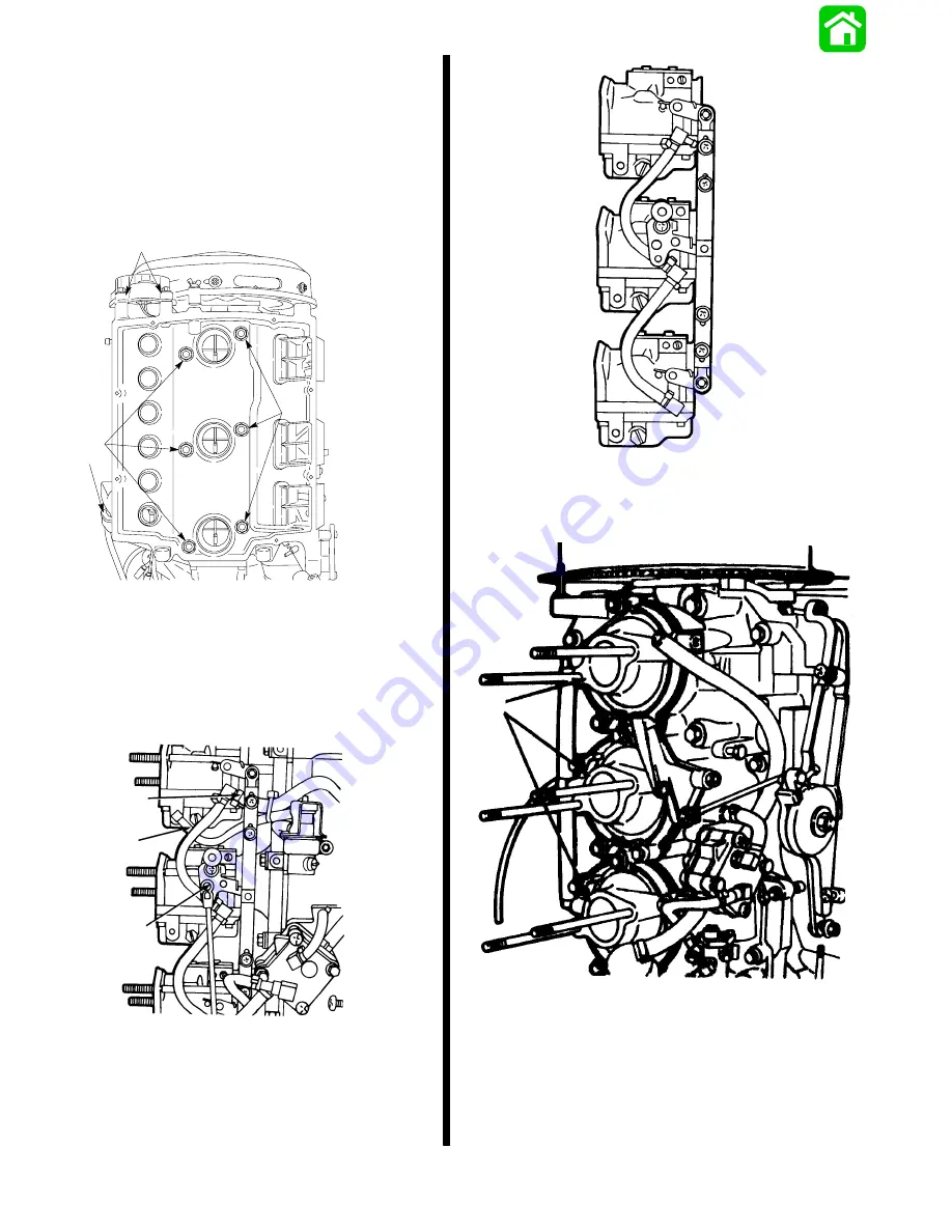
3. Remove 10mm bolt from lower oil tank support
(starboard side of engine, base).
4. Remove 2 (8mm) Bolts from upper oil tank neck
brace.
5. Remove Air Box by removing 6 nuts and pulling
off of carburetor studs.
6. Disconnect Oil Lines - Remove Oil Reservoir.
19097
a
b
c
c
a - Oil Tank Support
b - Bolts (8mm)
c - Nuts (6)
7. Disconnect Throttle Linkage (c).
8. Remove main fuel hose (a), and fuel hose (b). Lift
carburetors off as 1-unit assembly (see next col-
umn).
19093
a
b
c
a - Main Fuel Hose
b - Fuel Enrichment Hose
c - Throttle Linkage
9. Remove Flywheel Cover by removing 3 wing
nuts.
19546
1-unit Removal Of Carburetor Assembly.
10. Remove Intake Manifolds - see below.
19547
a
a - Intake Manifolds
Summary of Contents for 100
Page 4: ...GENERAL INFORMATION AND SPECIFICATIONS 1 ...
Page 18: ...IGNITION SYSTEM ELECTRICAL AND IGNITION A 2 ...
Page 30: ...11669 BATTERY CHARGING SYSTEM AND STARTING SYSTEM ELECTRICAL AND IGNITION B 2 ...
Page 58: ...22480 TIMING SYNCHRONIZING ADJUSTING ELECTRICAL AND IGNITION C 2 ...
Page 71: ...WIRING DIAGRAMS ELECTRICAL AND IGNITION D 2 ...
Page 86: ...FUEL SYSTEM AND CARBURETION A 3 ...
Page 118: ...OIL INJECTION SYSTEM B 3 ...
Page 127: ...20032 3 CYLINDER ENGINES POWERHEAD A 4 ...
Page 168: ...791 H GEAR HOUSING LOWER UNIT A 5 ...
Page 170: ...5A 1 90 13645 2 1095 LOWER UNIT Notes ...
Page 205: ...MID SECTION LOWER UNIT B 5 ...
Page 207: ...5B 1 90 13645 2 495 LOWER UNIT Notes ...
Page 218: ...SHOCK ABSORBER LOWER UNIT C 5 ...
Page 223: ...17250 DESIGN I SIDE FILL RESERVOIR POWER TRIM A 6 ...
Page 233: ...6A 9 POWER TRIM 90 13645 2 495 Commander Side Mount Remote Control Wiring Diagram ...
Page 268: ...DESIGN II AFT FILL RESERVOIR POWER TRIM B 6 51344 ...
Page 305: ...SINGLE RAM POWER TRIM C 6 51485 ...
Page 309: ...6C 3 90 13645 2 495 POWER TRIM Notes ...
Page 340: ...50099 ENGINE ATTACHMENTS ENGINE INSTALLATION 7 A ...
Page 369: ...TILLER HANDLE AND CO PILOT OUTBOARD MOTOR INSTALLATION ATTACHMENTS 7 B ...
Page 371: ...7B 1 90 13645 2 495 OUTBOARD MOTOR INSTALLATION ATTACHMENTS Notes ...