


7B-7
90-13645--2
495
OUTBOARD MOTOR INSTALLATION/ATTACHMENTS
Tiller Arm/Shift Lever
Removal
1. Remove BATTERY CABLES from BATTERY.
2. Remove outboard cowling.
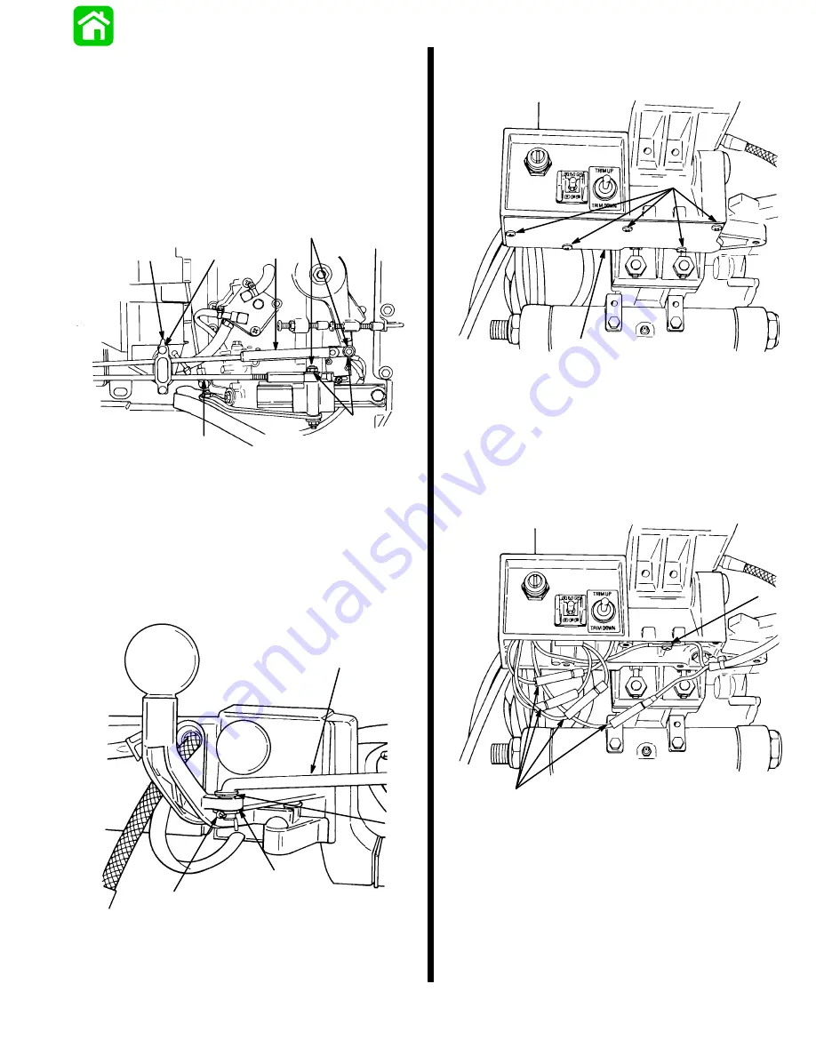
3. Remove nuts securing shift link rod and throttle
cable to engine. Release latch and remove shift
link rod and throttle cable from anchor bracket.
51620
a
b
c
d
e
f
a - Locking Nut
b - Washer
c - Shift Cable
d - Throttle Cable
e - Latch
f - Anchor Bracket
4. Remove cotter key, washer, bushing and shift link
rod from shift lever.
51624
a
b
c
d
a - Cotter Key
b - Washer
c - Bushing
d - Shift Link Rod
5. Remove access cover from underneath tiller
handle bracket.
51626
a
b
a - Access Cover
b - Screws
6. Disconnect key switch, lanyard stop switch and til-
ler stop switch leads at bullet connectors.
Remove screw securing key switch and tiller stop
switch ground leads.
51626
a
b
a - Bullet Connectors
b - Screw
Summary of Contents for 100
Page 4: ...GENERAL INFORMATION AND SPECIFICATIONS 1 ...
Page 18: ...IGNITION SYSTEM ELECTRICAL AND IGNITION A 2 ...
Page 30: ...11669 BATTERY CHARGING SYSTEM AND STARTING SYSTEM ELECTRICAL AND IGNITION B 2 ...
Page 58: ...22480 TIMING SYNCHRONIZING ADJUSTING ELECTRICAL AND IGNITION C 2 ...
Page 71: ...WIRING DIAGRAMS ELECTRICAL AND IGNITION D 2 ...
Page 86: ...FUEL SYSTEM AND CARBURETION A 3 ...
Page 118: ...OIL INJECTION SYSTEM B 3 ...
Page 127: ...20032 3 CYLINDER ENGINES POWERHEAD A 4 ...
Page 168: ...791 H GEAR HOUSING LOWER UNIT A 5 ...
Page 170: ...5A 1 90 13645 2 1095 LOWER UNIT Notes ...
Page 205: ...MID SECTION LOWER UNIT B 5 ...
Page 207: ...5B 1 90 13645 2 495 LOWER UNIT Notes ...
Page 218: ...SHOCK ABSORBER LOWER UNIT C 5 ...
Page 223: ...17250 DESIGN I SIDE FILL RESERVOIR POWER TRIM A 6 ...
Page 233: ...6A 9 POWER TRIM 90 13645 2 495 Commander Side Mount Remote Control Wiring Diagram ...
Page 268: ...DESIGN II AFT FILL RESERVOIR POWER TRIM B 6 51344 ...
Page 305: ...SINGLE RAM POWER TRIM C 6 51485 ...
Page 309: ...6C 3 90 13645 2 495 POWER TRIM Notes ...
Page 340: ...50099 ENGINE ATTACHMENTS ENGINE INSTALLATION 7 A ...
Page 369: ...TILLER HANDLE AND CO PILOT OUTBOARD MOTOR INSTALLATION ATTACHMENTS 7 B ...
Page 371: ...7B 1 90 13645 2 495 OUTBOARD MOTOR INSTALLATION ATTACHMENTS Notes ...