


90-13645--2
1095
5A-31
LOWER UNIT
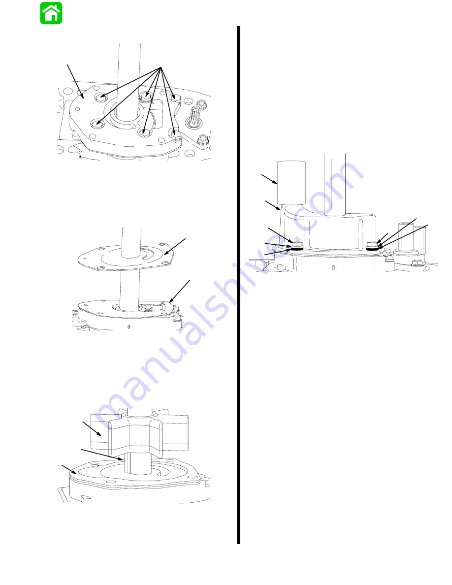
12. Install components as shown.
19217
a
b
a - Water Pump Base
b - Bolts and Washers; Apply Loctite 271 on Threads and
Torque to 60 lb. in. (6.8 N·m).
13. Install gasket and plate.
19219
a
b
a - Gasket
b - Plate
IMPORTANT: If the old impeller will be re-used,
impeller must be installed in original (clockwise)
direction of rotation.
14. Install gasket, drive key and impeller.
19220
a
b
c
a - Gasket
b - Drive Key
c - Impeller
15. Lubricate I.D. of cover with Quicksilver 2-4–C w/
Teflon (92-825407A12).
16. Rotate drive shaft clockwise and push cover
down over impeller.
17. Install cover.
18. If water tube seal stayed on water tube (inside of
drive shaft housing) when gear housing was re-
moved, pull water tube seal from water tube.
19. Lubricate I.D. of water tube seal with Quicksilver
2-4-C w/Teflon (92-825407A12) and install as
shown.
19212
a
b
c
d
c
d
b
e
a - Cover
b - Isolators (4) – If Equipped
c - Washers (4)
d - Bolts (4); Apply Loctite 271 on Threads and Torque to
60 lb. in. (6.8 N·m).
e - Water Tube Seal
NOTE: It is recommended that the gearcase be pres-
sure tested for leaks after reassembly and BEFORE
gear lube is added. Gearcase should hold 10 to 12 psi
for 5 minutes.
Summary of Contents for 100
Page 4: ...GENERAL INFORMATION AND SPECIFICATIONS 1 ...
Page 18: ...IGNITION SYSTEM ELECTRICAL AND IGNITION A 2 ...
Page 30: ...11669 BATTERY CHARGING SYSTEM AND STARTING SYSTEM ELECTRICAL AND IGNITION B 2 ...
Page 58: ...22480 TIMING SYNCHRONIZING ADJUSTING ELECTRICAL AND IGNITION C 2 ...
Page 71: ...WIRING DIAGRAMS ELECTRICAL AND IGNITION D 2 ...
Page 86: ...FUEL SYSTEM AND CARBURETION A 3 ...
Page 118: ...OIL INJECTION SYSTEM B 3 ...
Page 127: ...20032 3 CYLINDER ENGINES POWERHEAD A 4 ...
Page 168: ...791 H GEAR HOUSING LOWER UNIT A 5 ...
Page 170: ...5A 1 90 13645 2 1095 LOWER UNIT Notes ...
Page 205: ...MID SECTION LOWER UNIT B 5 ...
Page 207: ...5B 1 90 13645 2 495 LOWER UNIT Notes ...
Page 218: ...SHOCK ABSORBER LOWER UNIT C 5 ...
Page 223: ...17250 DESIGN I SIDE FILL RESERVOIR POWER TRIM A 6 ...
Page 233: ...6A 9 POWER TRIM 90 13645 2 495 Commander Side Mount Remote Control Wiring Diagram ...
Page 268: ...DESIGN II AFT FILL RESERVOIR POWER TRIM B 6 51344 ...
Page 305: ...SINGLE RAM POWER TRIM C 6 51485 ...
Page 309: ...6C 3 90 13645 2 495 POWER TRIM Notes ...
Page 340: ...50099 ENGINE ATTACHMENTS ENGINE INSTALLATION 7 A ...
Page 369: ...TILLER HANDLE AND CO PILOT OUTBOARD MOTOR INSTALLATION ATTACHMENTS 7 B ...
Page 371: ...7B 1 90 13645 2 495 OUTBOARD MOTOR INSTALLATION ATTACHMENTS Notes ...