


6C-21
90-13645--2
495
POWER-TRIM
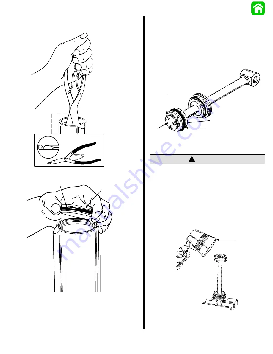
5. Remove memory piston from cylinder using lock-
ring pliers (Craftsman P/N 4735) or suitable tool.
51193
LOCK-RING PLIERS
6. Remove O-ring from memory piston.
51196
a
b
a - O-ring
b - Memory Piston
1. Place trim rod assembly on clean work surface.
2. Remove trim system from vise and empty fluid
into appropriate container.
Trim Rod Disassembly
1. Place trim rod assembly on clean work surface.
2. Remove screws securing plate to trim rod piston
and O-ring.
3. Remove check ball components from trim rod
piston.
51143
a
b
c
d
a - Screw (3)
b - Plate
c - O-ring
d - Piston
When removing Trim Rod piston, spanner wrench
must have 1/4 in. x 5/16 in. long pegs to avoid
damage to trim piston.
CAUTION
4. Place trim rod into soft jawed vise and apply heat
to shock piston using torch lamp (91-63209).
5. Loosen trim rod piston using spanner wrench
(1/4 in. x 5/16 in. long pegs).
6. Allow trim rod piston to cool. Remove from trim
rod.
51146
a
a - Torch Lamp
Summary of Contents for 100
Page 4: ...GENERAL INFORMATION AND SPECIFICATIONS 1 ...
Page 18: ...IGNITION SYSTEM ELECTRICAL AND IGNITION A 2 ...
Page 30: ...11669 BATTERY CHARGING SYSTEM AND STARTING SYSTEM ELECTRICAL AND IGNITION B 2 ...
Page 58: ...22480 TIMING SYNCHRONIZING ADJUSTING ELECTRICAL AND IGNITION C 2 ...
Page 71: ...WIRING DIAGRAMS ELECTRICAL AND IGNITION D 2 ...
Page 86: ...FUEL SYSTEM AND CARBURETION A 3 ...
Page 118: ...OIL INJECTION SYSTEM B 3 ...
Page 127: ...20032 3 CYLINDER ENGINES POWERHEAD A 4 ...
Page 168: ...791 H GEAR HOUSING LOWER UNIT A 5 ...
Page 170: ...5A 1 90 13645 2 1095 LOWER UNIT Notes ...
Page 205: ...MID SECTION LOWER UNIT B 5 ...
Page 207: ...5B 1 90 13645 2 495 LOWER UNIT Notes ...
Page 218: ...SHOCK ABSORBER LOWER UNIT C 5 ...
Page 223: ...17250 DESIGN I SIDE FILL RESERVOIR POWER TRIM A 6 ...
Page 233: ...6A 9 POWER TRIM 90 13645 2 495 Commander Side Mount Remote Control Wiring Diagram ...
Page 268: ...DESIGN II AFT FILL RESERVOIR POWER TRIM B 6 51344 ...
Page 305: ...SINGLE RAM POWER TRIM C 6 51485 ...
Page 309: ...6C 3 90 13645 2 495 POWER TRIM Notes ...
Page 340: ...50099 ENGINE ATTACHMENTS ENGINE INSTALLATION 7 A ...
Page 369: ...TILLER HANDLE AND CO PILOT OUTBOARD MOTOR INSTALLATION ATTACHMENTS 7 B ...
Page 371: ...7B 1 90 13645 2 495 OUTBOARD MOTOR INSTALLATION ATTACHMENTS Notes ...