


6A-19
POWER TRIM
90-13645--2
495
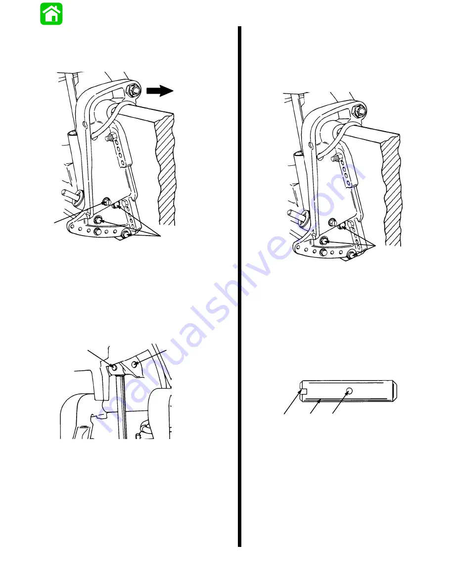
6. Remove 3 screws and washers and move
starboard transom bracket so that manual
release valve will clear bracket when power trim
is removed.
51375
a
b
c
a - Screws (3)
b - Washers (3)
c - Manual Release Valve
IMPORTANT: Cross pin (a) should not be reused.
Replace with new cross pin.
7. Drive out cross pin, push out upper swivel pin, and
remove 3 screws and washers retaining trim sys-
tem. Remove system from outboard.
51339
a
b
a - Cross Pin
b - Upper Swivel Pin
Installation
1. Paint any exposed metal surfaces to prevent
corrosion.
2. Apply Loctite 271 to screws. Install trim system,
starboard transom bracket, and tilt tube nut.
51375
a
b
a - Screw (6) Torque to 45 lb. ft. (61.0 N·m)
b - Flatwasher (6) Install one per screw
3. Use a 12 volt power source to extend tilt ram up
to align upper swivel shaft hole and end of ram.
Connect trim motor wires (BLUE wire to POS-
ITIVE (+), BLACK wire to NEGATIVE (-). If ram ex-
tends too far, retract ram by connecting GREEN
wire to POSITIVE (+).
4. Install Upper Swivel Pin with slotted end to left
(port) side of engine.
c
a
b
a - Upper Swivel Pin
b - Slotted End
c - Cross Hole (in line with slotted end)
IMPORTANT: Cross pin should not be reused.
Install a new pin.
Summary of Contents for 100
Page 4: ...GENERAL INFORMATION AND SPECIFICATIONS 1 ...
Page 18: ...IGNITION SYSTEM ELECTRICAL AND IGNITION A 2 ...
Page 30: ...11669 BATTERY CHARGING SYSTEM AND STARTING SYSTEM ELECTRICAL AND IGNITION B 2 ...
Page 58: ...22480 TIMING SYNCHRONIZING ADJUSTING ELECTRICAL AND IGNITION C 2 ...
Page 71: ...WIRING DIAGRAMS ELECTRICAL AND IGNITION D 2 ...
Page 86: ...FUEL SYSTEM AND CARBURETION A 3 ...
Page 118: ...OIL INJECTION SYSTEM B 3 ...
Page 127: ...20032 3 CYLINDER ENGINES POWERHEAD A 4 ...
Page 168: ...791 H GEAR HOUSING LOWER UNIT A 5 ...
Page 170: ...5A 1 90 13645 2 1095 LOWER UNIT Notes ...
Page 205: ...MID SECTION LOWER UNIT B 5 ...
Page 207: ...5B 1 90 13645 2 495 LOWER UNIT Notes ...
Page 218: ...SHOCK ABSORBER LOWER UNIT C 5 ...
Page 223: ...17250 DESIGN I SIDE FILL RESERVOIR POWER TRIM A 6 ...
Page 233: ...6A 9 POWER TRIM 90 13645 2 495 Commander Side Mount Remote Control Wiring Diagram ...
Page 268: ...DESIGN II AFT FILL RESERVOIR POWER TRIM B 6 51344 ...
Page 305: ...SINGLE RAM POWER TRIM C 6 51485 ...
Page 309: ...6C 3 90 13645 2 495 POWER TRIM Notes ...
Page 340: ...50099 ENGINE ATTACHMENTS ENGINE INSTALLATION 7 A ...
Page 369: ...TILLER HANDLE AND CO PILOT OUTBOARD MOTOR INSTALLATION ATTACHMENTS 7 B ...
Page 371: ...7B 1 90 13645 2 495 OUTBOARD MOTOR INSTALLATION ATTACHMENTS Notes ...