


90-13645--2
495
6B-17
POWER TRIM
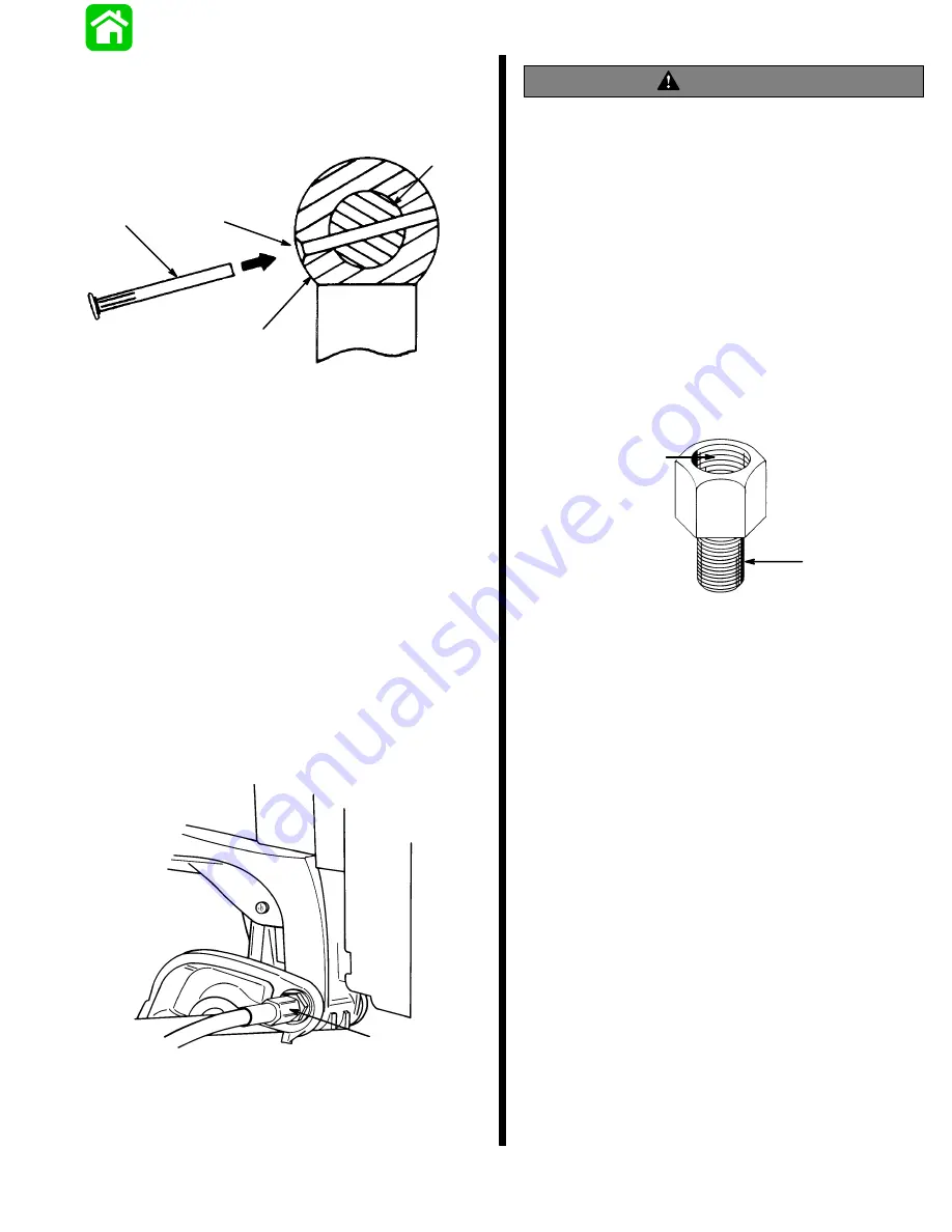
5. Position slot on end of swivel shaft in line with hole
in tilt ram end. Insert a punch into tilt ram hole to
align cross hole in upper swivel shaft. Tap new
cross pin in until flush.
b
c
d
a
a - Upper Swivel Shaft (Slot is in line with cross hole)
b - Chamfered End of Hole (Faces away from transom)
c - Retaining Pin
d - Tilt Ram End
6. Connect trim motor wires to solenoids. Refer to
Wiring Diagrams in this manual. Route trim wires
as specified in this manual.
7. Apply marine sealer to shanks of mount bolts and
install transom mount bolts.
IMPORTANT: Do not use an impact driver to tight-
en transom mount bolts.
Apply marine sealer to threads of mount bolts. Secure
with flat washers and locknuts. Be sure installation is
watertight.
8. Tighten tilt tube nut securely.
IMPORTANT: Outboards equipped with thru-the-
tilt-tube steering: Tighten steering cable retaining
nut securely to tilt tube.
51354
a
a - Steering Cable Retaining Nut
9. Apply Quicksilver Liquid Neoprene (91-25511--2)
on all electrical connections.
WARNING
Electrical wires passing through cowl openings
must be protected from chafing or being cut.
Follow the recommended procedures outlined in
Section 1 of this Manual. Failure to protect wires
as described could result in electrical system
failure and/or injury to occupants of boat.
Testing Power Trim System With Test Gauge Kit
(91-52915A3)
IMPORTANT: This test will not locate problems in
the trim system. The test will show if the system
is correct after a repair. If minimum pressures are
not obtainable, the trim system requires addition-
al repair.
Use Adapter Fitting (22-11243) to connect test gauge
to trim system.
3/8
″
-24 UNF
1/16
″
-27 NPSF
Summary of Contents for 100
Page 4: ...GENERAL INFORMATION AND SPECIFICATIONS 1 ...
Page 18: ...IGNITION SYSTEM ELECTRICAL AND IGNITION A 2 ...
Page 30: ...11669 BATTERY CHARGING SYSTEM AND STARTING SYSTEM ELECTRICAL AND IGNITION B 2 ...
Page 58: ...22480 TIMING SYNCHRONIZING ADJUSTING ELECTRICAL AND IGNITION C 2 ...
Page 71: ...WIRING DIAGRAMS ELECTRICAL AND IGNITION D 2 ...
Page 86: ...FUEL SYSTEM AND CARBURETION A 3 ...
Page 118: ...OIL INJECTION SYSTEM B 3 ...
Page 127: ...20032 3 CYLINDER ENGINES POWERHEAD A 4 ...
Page 168: ...791 H GEAR HOUSING LOWER UNIT A 5 ...
Page 170: ...5A 1 90 13645 2 1095 LOWER UNIT Notes ...
Page 205: ...MID SECTION LOWER UNIT B 5 ...
Page 207: ...5B 1 90 13645 2 495 LOWER UNIT Notes ...
Page 218: ...SHOCK ABSORBER LOWER UNIT C 5 ...
Page 223: ...17250 DESIGN I SIDE FILL RESERVOIR POWER TRIM A 6 ...
Page 233: ...6A 9 POWER TRIM 90 13645 2 495 Commander Side Mount Remote Control Wiring Diagram ...
Page 268: ...DESIGN II AFT FILL RESERVOIR POWER TRIM B 6 51344 ...
Page 305: ...SINGLE RAM POWER TRIM C 6 51485 ...
Page 309: ...6C 3 90 13645 2 495 POWER TRIM Notes ...
Page 340: ...50099 ENGINE ATTACHMENTS ENGINE INSTALLATION 7 A ...
Page 369: ...TILLER HANDLE AND CO PILOT OUTBOARD MOTOR INSTALLATION ATTACHMENTS 7 B ...
Page 371: ...7B 1 90 13645 2 495 OUTBOARD MOTOR INSTALLATION ATTACHMENTS Notes ...