


5A-32
LOWER UNIT
90-13645--2
1095
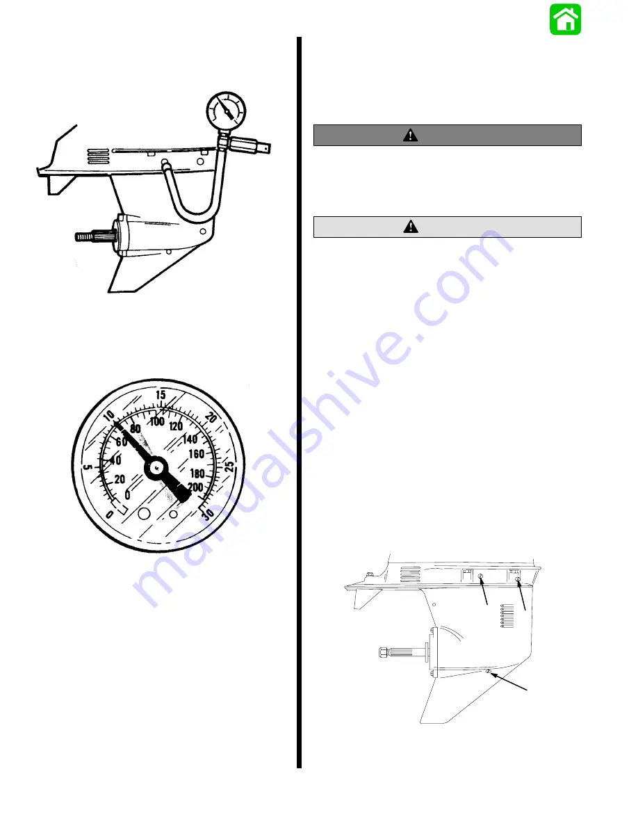
Gear Housing Pressure Test
1. Remove vent plug and install pressure test gauge
2. Pressurized housing to 10 to 12 psi and observe
gauge for 5 minutes.
3. Rotate drive shaft,prop shaft and move shift shaft
while housing is pressurized to check for leaks.
4. If pressure drop is noted, immerse housing in wa-
ter.
5. Re-pressurize to 10 to 12 psi and check for air
bubbles.
6. Replace leaking seals as necessary. Retest hous-
ing.
Note: Gearcase should hold 10 to 12 psi for 5 min-
utes.
7. Remove tester from housing and install vent plug.
Filling Gear Housing With
Lubricant
NOTE: Gear housing lubricant capacity is 22.5 fl. oz.
(665.2ml).
WARNING
If gear housing is installed on engine, to avoid
accidental starting, disconnect (and isolate)
spark plug leads from spark plugs before working
near the propeller.
Do not use automotive grease in the gear housing.
Use only Quicksilver Gear Lube or Quicksilver
Super-Duty Lower Unit Lubricant.
CAUTION
1. Remove any gasket material from “Fill” and “Vent”
screws and gear housing.
2. Install new gaskets on “Fill” and “Vent” screws.
IMPORTANT: Never apply lubricant to gear hous-
ing without first removing “Vent” screws or gear
housing cannot be filled because of trapped air.
Fill gear housing only when housing is in a verti-
cal position.
3. Remove lubricant “Fill” screw and gasket from
gear housing.
4. Insert lubricant tube into “Fill” hole, then remove
“Vent” screws and gaskets.
5. Fill gear housing with lubricant until excess starts
to flow out of one (first) “Vent” screw hole.
6. Replace this lubricant “Vent” screw and gasket
only and continue filling until excess starts to flow
out of second lubricant “Vent” screw hole.
51552
a
b
c
a - Vent Screw
b - Fill/Drain Screw
c - Oil Level Vent Screw
Summary of Contents for 100
Page 4: ...GENERAL INFORMATION AND SPECIFICATIONS 1 ...
Page 18: ...IGNITION SYSTEM ELECTRICAL AND IGNITION A 2 ...
Page 30: ...11669 BATTERY CHARGING SYSTEM AND STARTING SYSTEM ELECTRICAL AND IGNITION B 2 ...
Page 58: ...22480 TIMING SYNCHRONIZING ADJUSTING ELECTRICAL AND IGNITION C 2 ...
Page 71: ...WIRING DIAGRAMS ELECTRICAL AND IGNITION D 2 ...
Page 86: ...FUEL SYSTEM AND CARBURETION A 3 ...
Page 118: ...OIL INJECTION SYSTEM B 3 ...
Page 127: ...20032 3 CYLINDER ENGINES POWERHEAD A 4 ...
Page 168: ...791 H GEAR HOUSING LOWER UNIT A 5 ...
Page 170: ...5A 1 90 13645 2 1095 LOWER UNIT Notes ...
Page 205: ...MID SECTION LOWER UNIT B 5 ...
Page 207: ...5B 1 90 13645 2 495 LOWER UNIT Notes ...
Page 218: ...SHOCK ABSORBER LOWER UNIT C 5 ...
Page 223: ...17250 DESIGN I SIDE FILL RESERVOIR POWER TRIM A 6 ...
Page 233: ...6A 9 POWER TRIM 90 13645 2 495 Commander Side Mount Remote Control Wiring Diagram ...
Page 268: ...DESIGN II AFT FILL RESERVOIR POWER TRIM B 6 51344 ...
Page 305: ...SINGLE RAM POWER TRIM C 6 51485 ...
Page 309: ...6C 3 90 13645 2 495 POWER TRIM Notes ...
Page 340: ...50099 ENGINE ATTACHMENTS ENGINE INSTALLATION 7 A ...
Page 369: ...TILLER HANDLE AND CO PILOT OUTBOARD MOTOR INSTALLATION ATTACHMENTS 7 B ...
Page 371: ...7B 1 90 13645 2 495 OUTBOARD MOTOR INSTALLATION ATTACHMENTS Notes ...