


90-13645--2
495
6B-11
POWER TRIM
Electrical System
Troubleshooting
GENERAL CHECKS
Before troubleshooting the Power Trim electrical sys-
tem, check the following:
1. Check for disconnected wires.
2. Make certain all conditions are tight and corrosion
free.
3. Check that plug-in connectors are fully engaged.
4. Make certain battery is fully charged.
Refer to the preceding four wiring diagrams for
connection points when troubleshooting the electrical
systems (Connection points are specified by
number).
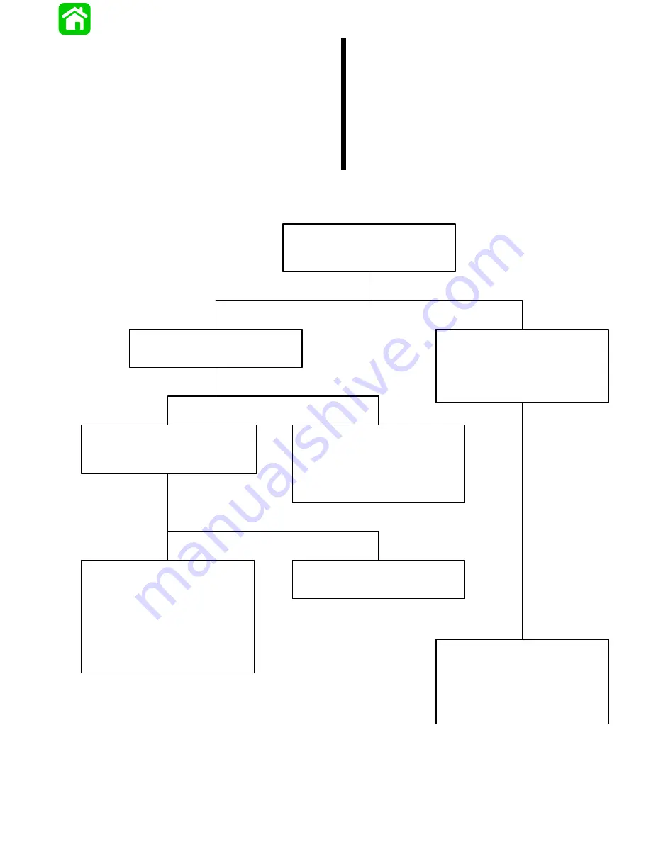
Troubleshooting the “Down” Circuit
(When “Up” Circuit is OK)
Battery Voltage Indicated:
Battery Voltage Indicated:
Battery Voltage Indicated:
No Voltage Indicated:
No Voltage Indicated:
No Voltage Indicated:
Solenoid is defective.
•
Connect Voltmeter RED lead to Point 2.
Connect Voltmeter RED lead to Point 9.
Connect Voltmeter RED lead to Point 4
and BLACK lead to ground. Depress
“Down” trim button. If battery voltage is
indicatied, wire is open between Points
4 and 1.
Depress the “Down” trim button.
•
Depress “Down” trim button.
•
Check “Down” solenoid terminals for
loose or corroded connections.
•
Check BLACK ground wire (on
“Down” solenoid) for corrosion or
open.
•
There is an open circuit between Point 9
and positive (+) battery terminal.
•
Check for loose or corroded connections.
•
Test “Down” solenoid. Refer to “Motor
and Electrical Tests”, see Index.
•
Check wires for open.
No Voltage Indicated:
Connect Voltmeter RED lead to Point 5.
If battery voltage is indicated, trim
switch is faulty. If no battery voltage,
check for loose or corroded connection
at Point 5 or open circuit in wire supply-
ing current to Point 5.
Connect Voltmeter RED lead to Point 1
and BLACK lead to ground.
Summary of Contents for 100
Page 4: ...GENERAL INFORMATION AND SPECIFICATIONS 1 ...
Page 18: ...IGNITION SYSTEM ELECTRICAL AND IGNITION A 2 ...
Page 30: ...11669 BATTERY CHARGING SYSTEM AND STARTING SYSTEM ELECTRICAL AND IGNITION B 2 ...
Page 58: ...22480 TIMING SYNCHRONIZING ADJUSTING ELECTRICAL AND IGNITION C 2 ...
Page 71: ...WIRING DIAGRAMS ELECTRICAL AND IGNITION D 2 ...
Page 86: ...FUEL SYSTEM AND CARBURETION A 3 ...
Page 118: ...OIL INJECTION SYSTEM B 3 ...
Page 127: ...20032 3 CYLINDER ENGINES POWERHEAD A 4 ...
Page 168: ...791 H GEAR HOUSING LOWER UNIT A 5 ...
Page 170: ...5A 1 90 13645 2 1095 LOWER UNIT Notes ...
Page 205: ...MID SECTION LOWER UNIT B 5 ...
Page 207: ...5B 1 90 13645 2 495 LOWER UNIT Notes ...
Page 218: ...SHOCK ABSORBER LOWER UNIT C 5 ...
Page 223: ...17250 DESIGN I SIDE FILL RESERVOIR POWER TRIM A 6 ...
Page 233: ...6A 9 POWER TRIM 90 13645 2 495 Commander Side Mount Remote Control Wiring Diagram ...
Page 268: ...DESIGN II AFT FILL RESERVOIR POWER TRIM B 6 51344 ...
Page 305: ...SINGLE RAM POWER TRIM C 6 51485 ...
Page 309: ...6C 3 90 13645 2 495 POWER TRIM Notes ...
Page 340: ...50099 ENGINE ATTACHMENTS ENGINE INSTALLATION 7 A ...
Page 369: ...TILLER HANDLE AND CO PILOT OUTBOARD MOTOR INSTALLATION ATTACHMENTS 7 B ...
Page 371: ...7B 1 90 13645 2 495 OUTBOARD MOTOR INSTALLATION ATTACHMENTS Notes ...