


7B-15
90-13645--2
495
OUTBOARD MOTOR INSTALLATION/ATTACHMENTS
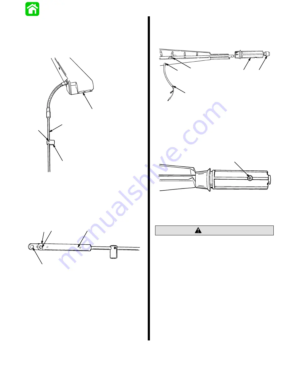
11. Slide brass barrel over throttle cable tube. Secure
barrel to tube with allen screw approximately
3.5 in. (89 mm) from stainless conduit. DO NOT
OVERTIGHTEN screw as tubing may be crushed
binding throttle cable. Position barrel to face to-
wards tiller handle.
51607
a
b
c
d
a - Brass Barrel
b - Tube
c - Allen Screw
d - Tiller Handle
12. Install throttle cable guide onto throttle cable. Se-
cure guide to cable with anchor and two screws.
Guide hole should face up.
51602
a
b
c
b
a - Cable Guide
b - Screws (2)
c - Hole (faces up)
13. Position throttle arm slot to face stop harness exit
hole in tiller handle. Route stop switch harness
through twist grip, into throttle arm, and out
through side of tiller handle.
51602
a
b
c
d
e
a - Slot
b - Exit Hole
c - Harness
d - Twist Grip
e - Stop Switch
14. Secure twist grip to throttle arm with attaching
screw.
51603
a
a - Screw
15. Sta-strap harness to throttle arm.
Allow enough slack in harness (rotate throttle grip
in both directions) before securing harness to
handle assembly with J-clip.
CAUTION
16. Attach harness to tiller arm with J-clip allowing
enough slack in harness for full throttle rotation.
Summary of Contents for 100
Page 4: ...GENERAL INFORMATION AND SPECIFICATIONS 1 ...
Page 18: ...IGNITION SYSTEM ELECTRICAL AND IGNITION A 2 ...
Page 30: ...11669 BATTERY CHARGING SYSTEM AND STARTING SYSTEM ELECTRICAL AND IGNITION B 2 ...
Page 58: ...22480 TIMING SYNCHRONIZING ADJUSTING ELECTRICAL AND IGNITION C 2 ...
Page 71: ...WIRING DIAGRAMS ELECTRICAL AND IGNITION D 2 ...
Page 86: ...FUEL SYSTEM AND CARBURETION A 3 ...
Page 118: ...OIL INJECTION SYSTEM B 3 ...
Page 127: ...20032 3 CYLINDER ENGINES POWERHEAD A 4 ...
Page 168: ...791 H GEAR HOUSING LOWER UNIT A 5 ...
Page 170: ...5A 1 90 13645 2 1095 LOWER UNIT Notes ...
Page 205: ...MID SECTION LOWER UNIT B 5 ...
Page 207: ...5B 1 90 13645 2 495 LOWER UNIT Notes ...
Page 218: ...SHOCK ABSORBER LOWER UNIT C 5 ...
Page 223: ...17250 DESIGN I SIDE FILL RESERVOIR POWER TRIM A 6 ...
Page 233: ...6A 9 POWER TRIM 90 13645 2 495 Commander Side Mount Remote Control Wiring Diagram ...
Page 268: ...DESIGN II AFT FILL RESERVOIR POWER TRIM B 6 51344 ...
Page 305: ...SINGLE RAM POWER TRIM C 6 51485 ...
Page 309: ...6C 3 90 13645 2 495 POWER TRIM Notes ...
Page 340: ...50099 ENGINE ATTACHMENTS ENGINE INSTALLATION 7 A ...
Page 369: ...TILLER HANDLE AND CO PILOT OUTBOARD MOTOR INSTALLATION ATTACHMENTS 7 B ...
Page 371: ...7B 1 90 13645 2 495 OUTBOARD MOTOR INSTALLATION ATTACHMENTS Notes ...