


7A-23
ENGINE ATTACHMENTS
90-13645--2
495
3. Adjust cable barrel to attain the same length be-
tween cable barrel and hole in end of cable guide
as exists between barrel retainer and shift actua-
tor stud, with a slight preload toward reverse.
4. Place end of shift cable on shift actuator stud then
place plastic washer on stud and secure with lock-
nut.
5. If used, remove tape from control handle.
6. Check shift cable adjustment as follows:
a. Shift remote control into forward gear. Now,
check prop shaft. The shaft should not be able
to turn counterclockwise. If it does, adjust cable
barrel closer to cable end guide.
b. Shift remote control into neutral. The prop
shaft now should turn freely without drag. If not,
adjust cable barrel away from cable end guide.
Repeat steps a and b.
c. Shift remote control into reverse as the prop
shaft is rotated by hand. The prop shaft
should not be able to turn in either direction. If
it does, adjust cable barrel away from cable end
guide. Repeat steps a thru c.
d. Shift remote control into neutral. The prop
shaft should turn freely without drag. If not, ad-
just cable barrel closer to cable end guide. Re-
peat steps a thru d.
22888
a
b
c
d
e
a - Cable Barrel
b - Barrel Retainer
c - Shift Actuator Stud
d - Plastic Washer
e - Locknut
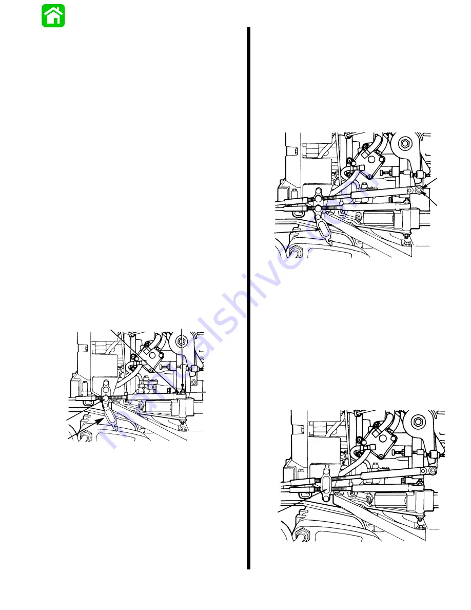
Throttle Cable Installation and
Adjustment to Engine
1. Shift remote control into neutral.
2. Attach end of throttle cable to stud on throttle lever
and secure with locknut as shown. Be sure to first
put on the cable end, then the plastic washer and
finally the locknut. Snug up the locknut and then
back off 1/4-turn.
22888
a
b
a - Locknut
b - Plastic Washer
3. Hold engine throttle lever against idle stop. Adjust
brass barrel so that there will be a slight preload
of throttle lever against the idle stop. Lock brass
barrels in place with barrel retainer.
4. Proper preload on throttle cable can be checked
by placing a piece of paper between idle stop
screw and idle stop. Preload is correct when the
paper can be removed without tearing but has
some drag on it. If necessary, readjust brass
barrel.
18432
a
a - Barrel Retainer
Summary of Contents for 100
Page 4: ...GENERAL INFORMATION AND SPECIFICATIONS 1 ...
Page 18: ...IGNITION SYSTEM ELECTRICAL AND IGNITION A 2 ...
Page 30: ...11669 BATTERY CHARGING SYSTEM AND STARTING SYSTEM ELECTRICAL AND IGNITION B 2 ...
Page 58: ...22480 TIMING SYNCHRONIZING ADJUSTING ELECTRICAL AND IGNITION C 2 ...
Page 71: ...WIRING DIAGRAMS ELECTRICAL AND IGNITION D 2 ...
Page 86: ...FUEL SYSTEM AND CARBURETION A 3 ...
Page 118: ...OIL INJECTION SYSTEM B 3 ...
Page 127: ...20032 3 CYLINDER ENGINES POWERHEAD A 4 ...
Page 168: ...791 H GEAR HOUSING LOWER UNIT A 5 ...
Page 170: ...5A 1 90 13645 2 1095 LOWER UNIT Notes ...
Page 205: ...MID SECTION LOWER UNIT B 5 ...
Page 207: ...5B 1 90 13645 2 495 LOWER UNIT Notes ...
Page 218: ...SHOCK ABSORBER LOWER UNIT C 5 ...
Page 223: ...17250 DESIGN I SIDE FILL RESERVOIR POWER TRIM A 6 ...
Page 233: ...6A 9 POWER TRIM 90 13645 2 495 Commander Side Mount Remote Control Wiring Diagram ...
Page 268: ...DESIGN II AFT FILL RESERVOIR POWER TRIM B 6 51344 ...
Page 305: ...SINGLE RAM POWER TRIM C 6 51485 ...
Page 309: ...6C 3 90 13645 2 495 POWER TRIM Notes ...
Page 340: ...50099 ENGINE ATTACHMENTS ENGINE INSTALLATION 7 A ...
Page 369: ...TILLER HANDLE AND CO PILOT OUTBOARD MOTOR INSTALLATION ATTACHMENTS 7 B ...
Page 371: ...7B 1 90 13645 2 495 OUTBOARD MOTOR INSTALLATION ATTACHMENTS Notes ...