


90-13645--2
1095
5A-29
LOWER UNIT
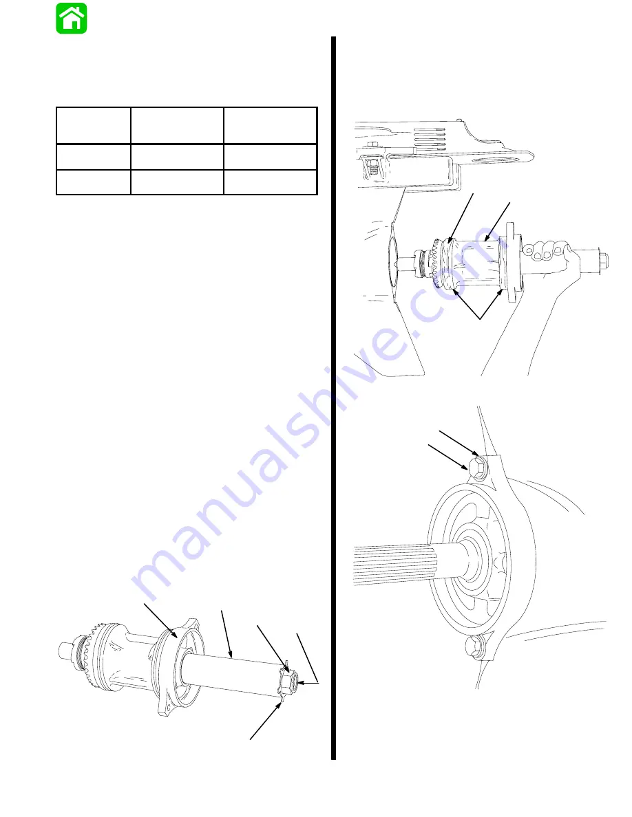
7. Lightly turn drive shaft back-and-forth (no move-
ment should be noticed at propeller shaft).
8. Dial Indicator registers amount of backlash, which
must be between specification shown in chart.
MODEL
DIAL
INDICATOR
MINIMUM
READING
MAXIMUM
75-thru-90
(3 Cylinder)
0.012 in.
(0.30mm)
0.019 in.
(.48mm)
100/115/125
(4 Cylinder)
0.015 in.
(0.38mm)
0.022 in.
(0.55mm)
9. If backlash is less than the minimum specification,
remove shim(s)* from in front of forward gear
bearing race to obtain correct backlash. When re-
installing pinion nut, apply Loctite 271 on threads
of nut.
10. If backlash is more than the maximum specifica-
tion, add shim(s)* in front of forward gear bearing
race to obtain correct backlash. When reinstalling
pinion nut, apply Loctite 271 on threads of nut.
*
By adding or subtracting 0.001
(0.025mm) shim, the back-
lash will change approximately 0.001
(.025mm).
Bearing Carrier and Propeller Shaft
Installation
1. Insert propeller shaft assembly into bearing
carrier.
2. Before installing bearing carrier assembly into
gear housing, obtain locally a 6
(152.4mm) long
by 1-1/4
– 1-1/2
(31.7 – 38.1mm) diameter
piece of PVC pipe. Install the PVC pipe (f) over the
prop shaft (a) and secure the pipe against the
bearing carrier assembly (b) with the propeller nut
(g) and tab washer (h). This will allow the reverse
gear to apply pressure to the reverse gear thrust
bearing to prevent the thrust bearing from being
inadvertently dislodged as the bearing carrier
assembly is installed in the gear housing.
21043
a
b
c
d
e
f
g
h
3. Lubricate o-ring (c) and areas (d) with 2-4-C w/
Teflon (92-825407A12).
4. Install bearing carrier and propeller shaft into
housing with the word “TOP” located on flange (e)
toward top of housing.
21044
a
b
c
d
e
5. Install components as shown.
19147
a
b
a - Washers
b - Bolts; Apply Loctite 271 on Threads and Torque to 21.7 lb. ft.
(29.4 N·m)
NOTE: If nuts are used in place of bolts (b), torque
nuts to 21.7 lb. ft. (29.4 N·m).
Summary of Contents for 100
Page 4: ...GENERAL INFORMATION AND SPECIFICATIONS 1 ...
Page 18: ...IGNITION SYSTEM ELECTRICAL AND IGNITION A 2 ...
Page 30: ...11669 BATTERY CHARGING SYSTEM AND STARTING SYSTEM ELECTRICAL AND IGNITION B 2 ...
Page 58: ...22480 TIMING SYNCHRONIZING ADJUSTING ELECTRICAL AND IGNITION C 2 ...
Page 71: ...WIRING DIAGRAMS ELECTRICAL AND IGNITION D 2 ...
Page 86: ...FUEL SYSTEM AND CARBURETION A 3 ...
Page 118: ...OIL INJECTION SYSTEM B 3 ...
Page 127: ...20032 3 CYLINDER ENGINES POWERHEAD A 4 ...
Page 168: ...791 H GEAR HOUSING LOWER UNIT A 5 ...
Page 170: ...5A 1 90 13645 2 1095 LOWER UNIT Notes ...
Page 205: ...MID SECTION LOWER UNIT B 5 ...
Page 207: ...5B 1 90 13645 2 495 LOWER UNIT Notes ...
Page 218: ...SHOCK ABSORBER LOWER UNIT C 5 ...
Page 223: ...17250 DESIGN I SIDE FILL RESERVOIR POWER TRIM A 6 ...
Page 233: ...6A 9 POWER TRIM 90 13645 2 495 Commander Side Mount Remote Control Wiring Diagram ...
Page 268: ...DESIGN II AFT FILL RESERVOIR POWER TRIM B 6 51344 ...
Page 305: ...SINGLE RAM POWER TRIM C 6 51485 ...
Page 309: ...6C 3 90 13645 2 495 POWER TRIM Notes ...
Page 340: ...50099 ENGINE ATTACHMENTS ENGINE INSTALLATION 7 A ...
Page 369: ...TILLER HANDLE AND CO PILOT OUTBOARD MOTOR INSTALLATION ATTACHMENTS 7 B ...
Page 371: ...7B 1 90 13645 2 495 OUTBOARD MOTOR INSTALLATION ATTACHMENTS Notes ...