


6C-25
90-13645--2
495
POWER-TRIM
3. Remove O-rings from cylinder.
51008
a
a - O-rings
Cleaning and Inspection of
Trim Rod Components
Do not remove check ball components (a) from
trim rod piston. Removal and re-installation of
check valve could result in improper operating
pressure and possible power trim system
damage.
CAUTION
51199
a
a - Check Ball Components
Inspect check valve for debris; clean debris form
check valve if found. If debris cannot be cleaned from
check valve, replace trim rod piston as an assembly.
Clean trim rod and components with parts cleaner
and dry with compressed air.
It is recommended that all O-rings in trim system be
replaced.
Inspect trim rod. If scraper (located in cap) has failed
to keep rod clean, replace scraper.
Lubricate all O-rings using Quicksilver Power Trim
and Steering Fluid or; (ATF) Type F, FA or Dexron II.
Motor and Electrical
Tests/Repair
Trim Pump Motor Test
WARNING
Do not perform this test near flammables (or
explosives), as a spark may occur when making
connections.
1. Disconnect GREEN (motor) wire and BLUE (mo-
tor) wire from trim system wiring harness.
2. Connect a 12 volt power supply to motor wires
(POSITIVE to BLUE; NEGATIVE to GREEN re-
sults in motor up direction. POSITIVE to GREEN;
NEGATIVE to BLUE results in motor down direc-
tion). Motor should run.
3. If motor does not run, disassemble motor and
check components.
Armature Tests
TEST FOR SHORTS
Check armature on a Growler (follow Growler man-
ufacturer’s test instructions). Indication of a short re-
quires replacement of armature.
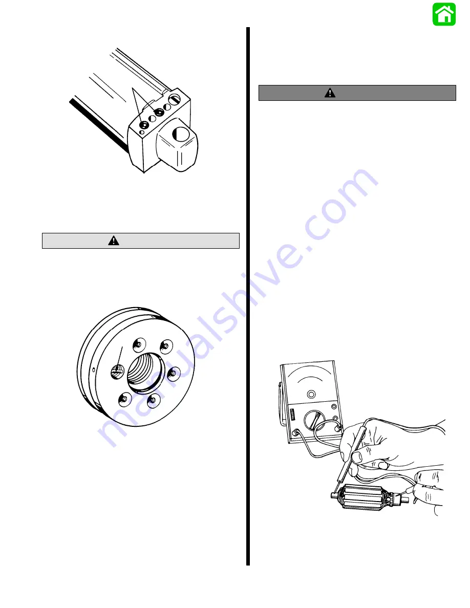
TEST FOR GROUND
Use an Ohmmeter (R x 1 scale). Place one lead on
Ohmmeter on armature shaft and other lead on com-
mutator, as shown. If continuity is indicated, armature
is grounded and must be replaced.
51195
Summary of Contents for 100
Page 4: ...GENERAL INFORMATION AND SPECIFICATIONS 1 ...
Page 18: ...IGNITION SYSTEM ELECTRICAL AND IGNITION A 2 ...
Page 30: ...11669 BATTERY CHARGING SYSTEM AND STARTING SYSTEM ELECTRICAL AND IGNITION B 2 ...
Page 58: ...22480 TIMING SYNCHRONIZING ADJUSTING ELECTRICAL AND IGNITION C 2 ...
Page 71: ...WIRING DIAGRAMS ELECTRICAL AND IGNITION D 2 ...
Page 86: ...FUEL SYSTEM AND CARBURETION A 3 ...
Page 118: ...OIL INJECTION SYSTEM B 3 ...
Page 127: ...20032 3 CYLINDER ENGINES POWERHEAD A 4 ...
Page 168: ...791 H GEAR HOUSING LOWER UNIT A 5 ...
Page 170: ...5A 1 90 13645 2 1095 LOWER UNIT Notes ...
Page 205: ...MID SECTION LOWER UNIT B 5 ...
Page 207: ...5B 1 90 13645 2 495 LOWER UNIT Notes ...
Page 218: ...SHOCK ABSORBER LOWER UNIT C 5 ...
Page 223: ...17250 DESIGN I SIDE FILL RESERVOIR POWER TRIM A 6 ...
Page 233: ...6A 9 POWER TRIM 90 13645 2 495 Commander Side Mount Remote Control Wiring Diagram ...
Page 268: ...DESIGN II AFT FILL RESERVOIR POWER TRIM B 6 51344 ...
Page 305: ...SINGLE RAM POWER TRIM C 6 51485 ...
Page 309: ...6C 3 90 13645 2 495 POWER TRIM Notes ...
Page 340: ...50099 ENGINE ATTACHMENTS ENGINE INSTALLATION 7 A ...
Page 369: ...TILLER HANDLE AND CO PILOT OUTBOARD MOTOR INSTALLATION ATTACHMENTS 7 B ...
Page 371: ...7B 1 90 13645 2 495 OUTBOARD MOTOR INSTALLATION ATTACHMENTS Notes ...