


6A-32
POWER TRIM
90-13645--2
495
REASSEMBLY
IMPORTANT: Components must be dirt and lint
free. Slightest amount of debris in Power Trim
system could cause system to malfunction.
1. Apply Automatic Transmission Fluid (ATF) Type A
(Dexron II) on O-rings during reassembly.
NOTE: Refer to “Tilt Ram Components” for proper
O-ring sizes.
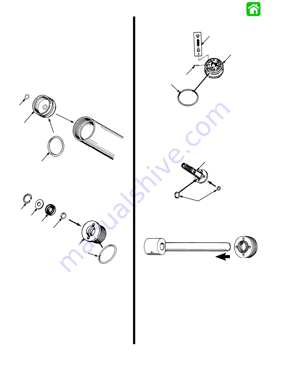
Install O-rings.
2. Insert cup into housing.
a
b
51372
a
a - O-ring
b - Memory Piston Cup (Design 1 shown)
3. Assemble cap, as shown.
c
a
b
d
e
b
a - End Cap
b - O-ring (2)
c - Scraper Seal
d - Washer
e - Retaining Ring
4. Install components, as shown.
a
b
c
d
a - Piston
b - Roll Pin
c - Check Valve Assembly
d - O-ring
5. Install O-rings in locations shown.
a
b
a - Rod End
b - O-rings
6. Install end cap.
51376
NOTE: Some tilt rams have one check valve spring
that is a lighter duty than the other six springs.
7. Install components onto rod, as shown.
Summary of Contents for 100
Page 4: ...GENERAL INFORMATION AND SPECIFICATIONS 1 ...
Page 18: ...IGNITION SYSTEM ELECTRICAL AND IGNITION A 2 ...
Page 30: ...11669 BATTERY CHARGING SYSTEM AND STARTING SYSTEM ELECTRICAL AND IGNITION B 2 ...
Page 58: ...22480 TIMING SYNCHRONIZING ADJUSTING ELECTRICAL AND IGNITION C 2 ...
Page 71: ...WIRING DIAGRAMS ELECTRICAL AND IGNITION D 2 ...
Page 86: ...FUEL SYSTEM AND CARBURETION A 3 ...
Page 118: ...OIL INJECTION SYSTEM B 3 ...
Page 127: ...20032 3 CYLINDER ENGINES POWERHEAD A 4 ...
Page 168: ...791 H GEAR HOUSING LOWER UNIT A 5 ...
Page 170: ...5A 1 90 13645 2 1095 LOWER UNIT Notes ...
Page 205: ...MID SECTION LOWER UNIT B 5 ...
Page 207: ...5B 1 90 13645 2 495 LOWER UNIT Notes ...
Page 218: ...SHOCK ABSORBER LOWER UNIT C 5 ...
Page 223: ...17250 DESIGN I SIDE FILL RESERVOIR POWER TRIM A 6 ...
Page 233: ...6A 9 POWER TRIM 90 13645 2 495 Commander Side Mount Remote Control Wiring Diagram ...
Page 268: ...DESIGN II AFT FILL RESERVOIR POWER TRIM B 6 51344 ...
Page 305: ...SINGLE RAM POWER TRIM C 6 51485 ...
Page 309: ...6C 3 90 13645 2 495 POWER TRIM Notes ...
Page 340: ...50099 ENGINE ATTACHMENTS ENGINE INSTALLATION 7 A ...
Page 369: ...TILLER HANDLE AND CO PILOT OUTBOARD MOTOR INSTALLATION ATTACHMENTS 7 B ...
Page 371: ...7B 1 90 13645 2 495 OUTBOARD MOTOR INSTALLATION ATTACHMENTS Notes ...