


5A-10
LOWER UNIT
90-13645--2
1095
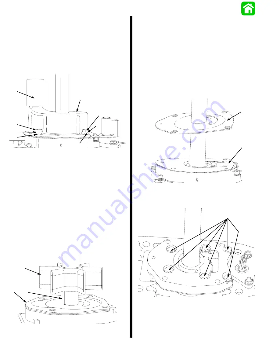
Water Pump (Design 1)
1. If water tube seal stayed on water tube (inside of
drive shaft housing) when gear housing was
removed, pull water tube seal from water tube.
2. Replace water tube seal, if damaged.
3. Remove 4 bolts, washers, and isolators.
4. Remove cover.
19212
a
b
c
d
e
c
d
b
a - Water Tube Seal
b - Bolts (4 each)
c - Washers (4 each)
d - Isolators (4 each)
e - Cover
IMPORTANT: The circular groove formed by the
impeller sealing bead should be disregarded
when inspecting cover (Step 5) and plate (Step 9),
as the depth of the groove will not affect water
pump output.
5. Replace cover if thickness of steel at the dis-
charge slots is 0.060
or less, or if groove(s) (oth-
er than impeller sealing bead groove) in cover roof
are more than 0.030
(0.762mm) deep.
6. Lift impeller, drive key, and gasket from drive
shaft.
a
b
c
19220
a - Impeller
b - Drive Key
c - Gasket
7. Inspect impeller. Replace impeller if any of the
following conditions exist:
– Impeller blade(s) are cracked, torn, or worn.
– Impeller is glazed or melted (caused by opera-
tion without sufficient water supply).
– Rubber portion of impeller is not bonded to
impeller hub.
8. Remove plate and gasket.
9. Replace plate if groove(s) (other than impeller
sealing bead groove) in plate are more than
0.030
(0.762mm) deep.
19219
a
b
a - Plate
b - Gasket
10. Remove bolts and washers.
a
19217
a - Bolts and Washers (6 each)
Summary of Contents for 100
Page 4: ...GENERAL INFORMATION AND SPECIFICATIONS 1 ...
Page 18: ...IGNITION SYSTEM ELECTRICAL AND IGNITION A 2 ...
Page 30: ...11669 BATTERY CHARGING SYSTEM AND STARTING SYSTEM ELECTRICAL AND IGNITION B 2 ...
Page 58: ...22480 TIMING SYNCHRONIZING ADJUSTING ELECTRICAL AND IGNITION C 2 ...
Page 71: ...WIRING DIAGRAMS ELECTRICAL AND IGNITION D 2 ...
Page 86: ...FUEL SYSTEM AND CARBURETION A 3 ...
Page 118: ...OIL INJECTION SYSTEM B 3 ...
Page 127: ...20032 3 CYLINDER ENGINES POWERHEAD A 4 ...
Page 168: ...791 H GEAR HOUSING LOWER UNIT A 5 ...
Page 170: ...5A 1 90 13645 2 1095 LOWER UNIT Notes ...
Page 205: ...MID SECTION LOWER UNIT B 5 ...
Page 207: ...5B 1 90 13645 2 495 LOWER UNIT Notes ...
Page 218: ...SHOCK ABSORBER LOWER UNIT C 5 ...
Page 223: ...17250 DESIGN I SIDE FILL RESERVOIR POWER TRIM A 6 ...
Page 233: ...6A 9 POWER TRIM 90 13645 2 495 Commander Side Mount Remote Control Wiring Diagram ...
Page 268: ...DESIGN II AFT FILL RESERVOIR POWER TRIM B 6 51344 ...
Page 305: ...SINGLE RAM POWER TRIM C 6 51485 ...
Page 309: ...6C 3 90 13645 2 495 POWER TRIM Notes ...
Page 340: ...50099 ENGINE ATTACHMENTS ENGINE INSTALLATION 7 A ...
Page 369: ...TILLER HANDLE AND CO PILOT OUTBOARD MOTOR INSTALLATION ATTACHMENTS 7 B ...
Page 371: ...7B 1 90 13645 2 495 OUTBOARD MOTOR INSTALLATION ATTACHMENTS Notes ...