


4A-20
90-13645--2
495
POWERHEAD
a
b
c
d
a - Crankcase Cover
b - Check Valve Assembly P/N 21-42657A1
c - Valve Restrictor P/N 22-814204
d - Install From Crankshaft Side
Check Valve/Restrictor Assembly
7. Verify check balls are free to move in check valve
case after installation. If check balls are not loose,
check valve case was damaged during installa-
tion and MUST BE replaced.
8. Reassemble powerhead per appropriate service
manual instructions and reinstall on driveshaft
housing.
DESIGN 3 (MODELS WITH CHECK VALVE AND
CARRIER)
NOTE: DESIGN 3 check valves may be replaced
without splitting crankcase halves.
REMOVAL
1. Remove carburetors and intake manifold/reed
block assemblies. Refer to page 4A-10/11 for
procedure.
2. Grasp carrier and remove carrier/check valve as-
sembly from crankcase cover.
51621
a
a - Carrier/Check Valve Assembly
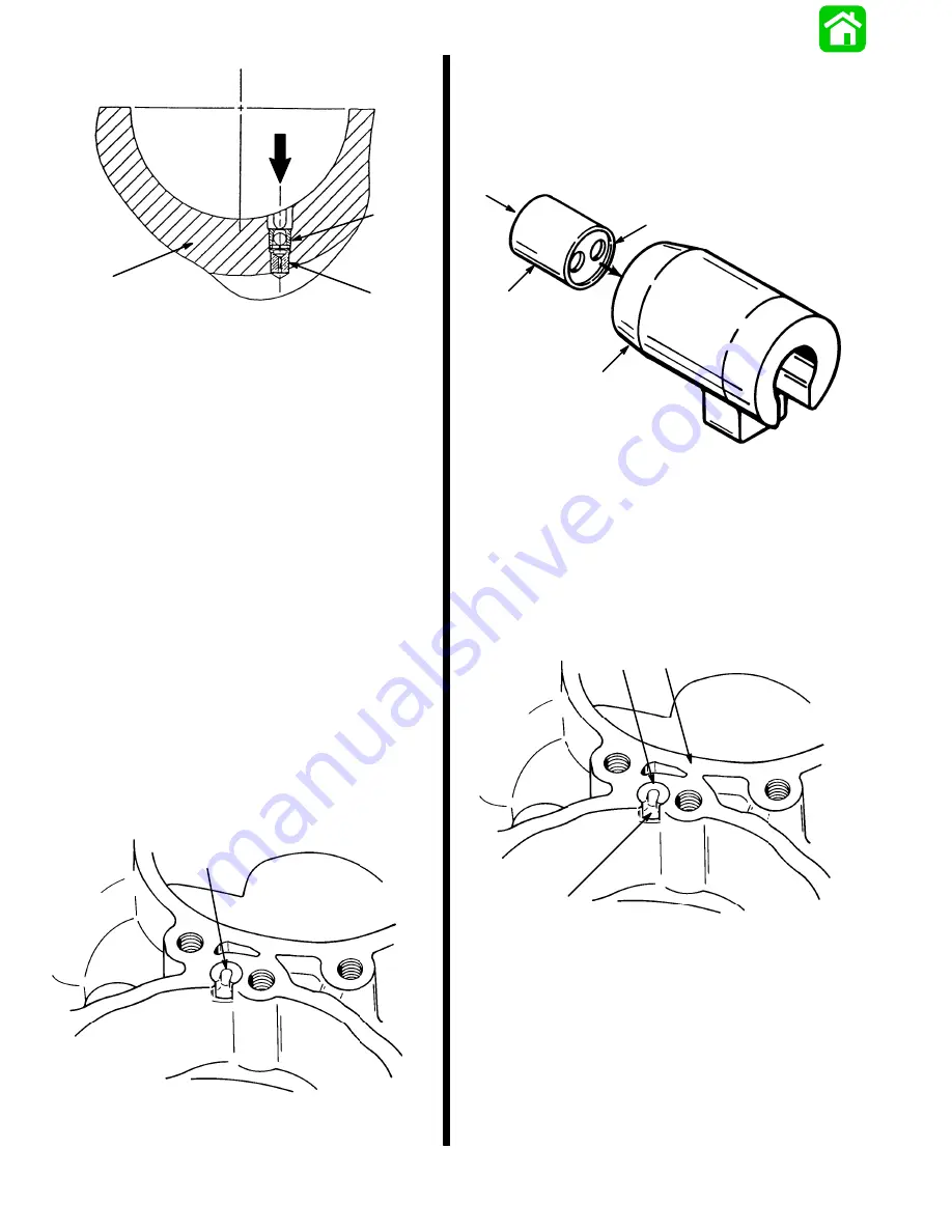
3. Push check valve out of carrier. If nylon ball within
check valve is stuck or carrier is charred, replace
check valve and/or carrier as required.
IMPORTANT: SINGLE HOLE side of check valve
MUST FACE CRANKCASE.
51131
a
b
c
d
a - Check Valve
b - Carrier
c - Single Hole
d - Double Hole
INSTALLATION
1. Install check valve (if removed) inside of carrier
(single hole of valve faces tapered end of carrier).
2. Align carrier tab with slot in crankcase cover and
insert check valve/carrier assembly into cover.
51621
a
b
c
a - Check Valve/Carrier Assembly
b - Slot
c - Crankcase Cover
Summary of Contents for 100
Page 4: ...GENERAL INFORMATION AND SPECIFICATIONS 1 ...
Page 18: ...IGNITION SYSTEM ELECTRICAL AND IGNITION A 2 ...
Page 30: ...11669 BATTERY CHARGING SYSTEM AND STARTING SYSTEM ELECTRICAL AND IGNITION B 2 ...
Page 58: ...22480 TIMING SYNCHRONIZING ADJUSTING ELECTRICAL AND IGNITION C 2 ...
Page 71: ...WIRING DIAGRAMS ELECTRICAL AND IGNITION D 2 ...
Page 86: ...FUEL SYSTEM AND CARBURETION A 3 ...
Page 118: ...OIL INJECTION SYSTEM B 3 ...
Page 127: ...20032 3 CYLINDER ENGINES POWERHEAD A 4 ...
Page 168: ...791 H GEAR HOUSING LOWER UNIT A 5 ...
Page 170: ...5A 1 90 13645 2 1095 LOWER UNIT Notes ...
Page 205: ...MID SECTION LOWER UNIT B 5 ...
Page 207: ...5B 1 90 13645 2 495 LOWER UNIT Notes ...
Page 218: ...SHOCK ABSORBER LOWER UNIT C 5 ...
Page 223: ...17250 DESIGN I SIDE FILL RESERVOIR POWER TRIM A 6 ...
Page 233: ...6A 9 POWER TRIM 90 13645 2 495 Commander Side Mount Remote Control Wiring Diagram ...
Page 268: ...DESIGN II AFT FILL RESERVOIR POWER TRIM B 6 51344 ...
Page 305: ...SINGLE RAM POWER TRIM C 6 51485 ...
Page 309: ...6C 3 90 13645 2 495 POWER TRIM Notes ...
Page 340: ...50099 ENGINE ATTACHMENTS ENGINE INSTALLATION 7 A ...
Page 369: ...TILLER HANDLE AND CO PILOT OUTBOARD MOTOR INSTALLATION ATTACHMENTS 7 B ...
Page 371: ...7B 1 90 13645 2 495 OUTBOARD MOTOR INSTALLATION ATTACHMENTS Notes ...