


90-13645--2
495
7B-20
OUTBOARD MOTOR INSTALLATION/ATTACHMENTS
Shift Link Rod Installation
and Adjustment to Engine
1. Position shift lever handle into neutral detent.
2. Manually shift outboard into neutral (propeller will
rotate freely).
3. Adjust shift link rod end to slip over shift actuator
bolt with slight preload adjustment toward re-
verse.
4. Place hole in end of shift link rod end over stud of
shift actuator and secure with lock nut and wash-
er. Tighten until snug then back off 1/4 turn.
51622
a
b
c
a - Shift Link Rod End
b - Shift Actuator Stud
c - Lock Nut
5. Check shift link rod adjustment as follows:
a. Place engine shift lever in “F” (Forward) posi-
tion. Propeller should not rotate in a COUN-
TERCLOCKWISE direction. If propeller does
rotate COUNTERCLOCKWISE, length of shift
link rod must be reduced and Step “a” repeated.
b. Place engine shift lever in “N” (Neutral) position.
Propeller should rotate freely without drag. If
not, length of shift link rod must be increased
and Steps “a” and “b” repeated
c. While rotating propeller, place engine shift lever
in “R” (Reverse) position. If propeller can be ro-
tated in either direction, length of shift link rod
must be increased and Steps “a” thru “c” re-
peated.
d. Place engine shift lever in “N” (Neutral) position.
Propeller should turn freely without drag. If not,
length of shift link rod must be decreased and
Steps “a” thru “d” repeated.
Throttle Cable Installation
and Adjustment to Engine
IMPORTANT: Turn throttle cable conduit
clockwise until bottomed on tiller handle then
back off one turn before reconnecting throttle
cable to engine.
1. Rotate throttle twist grip fully clockwise to stop
“IDLE” position.
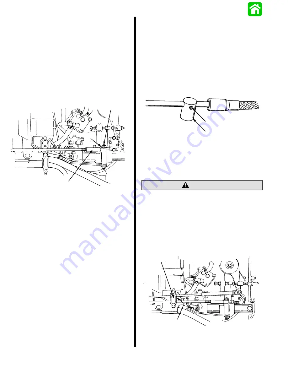
2. Back out set screw from throttle cable barrel until
2 or 3 threads of set screw are exposed.
51077
a
b
a - Set Screw
b - Throttle Cable Barrel
3. Place end of throttle cable guide over peg of
throttle lever and secure with locknut and washer.
Tighten until snug then back off 1/4 turn.
DO NOT exceed 1/4 turn on set screw after it has
bottomed-out.
CAUTION
4. Holding engine throttle lever against idle stop, ad-
just throttle cable barrel to slip into upper hole of
barrel receptacle, with a very light preload of
throttle lever against idle stop. Apply small
amount of Loctite 271 to threads of allen screw
and tighten until snug, then an additional 1/8 turn.
Lock barrel in place with barrel retainer.
c
d
51620
c - Barrel Receptacle
d - Barrel Retainer
Summary of Contents for 100
Page 4: ...GENERAL INFORMATION AND SPECIFICATIONS 1 ...
Page 18: ...IGNITION SYSTEM ELECTRICAL AND IGNITION A 2 ...
Page 30: ...11669 BATTERY CHARGING SYSTEM AND STARTING SYSTEM ELECTRICAL AND IGNITION B 2 ...
Page 58: ...22480 TIMING SYNCHRONIZING ADJUSTING ELECTRICAL AND IGNITION C 2 ...
Page 71: ...WIRING DIAGRAMS ELECTRICAL AND IGNITION D 2 ...
Page 86: ...FUEL SYSTEM AND CARBURETION A 3 ...
Page 118: ...OIL INJECTION SYSTEM B 3 ...
Page 127: ...20032 3 CYLINDER ENGINES POWERHEAD A 4 ...
Page 168: ...791 H GEAR HOUSING LOWER UNIT A 5 ...
Page 170: ...5A 1 90 13645 2 1095 LOWER UNIT Notes ...
Page 205: ...MID SECTION LOWER UNIT B 5 ...
Page 207: ...5B 1 90 13645 2 495 LOWER UNIT Notes ...
Page 218: ...SHOCK ABSORBER LOWER UNIT C 5 ...
Page 223: ...17250 DESIGN I SIDE FILL RESERVOIR POWER TRIM A 6 ...
Page 233: ...6A 9 POWER TRIM 90 13645 2 495 Commander Side Mount Remote Control Wiring Diagram ...
Page 268: ...DESIGN II AFT FILL RESERVOIR POWER TRIM B 6 51344 ...
Page 305: ...SINGLE RAM POWER TRIM C 6 51485 ...
Page 309: ...6C 3 90 13645 2 495 POWER TRIM Notes ...
Page 340: ...50099 ENGINE ATTACHMENTS ENGINE INSTALLATION 7 A ...
Page 369: ...TILLER HANDLE AND CO PILOT OUTBOARD MOTOR INSTALLATION ATTACHMENTS 7 B ...
Page 371: ...7B 1 90 13645 2 495 OUTBOARD MOTOR INSTALLATION ATTACHMENTS Notes ...