


6C-20
90-13645--2
495
POWER-TRIM
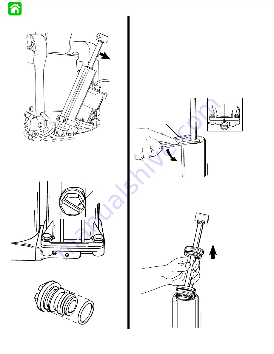
8. Tilt power trim assembly (top first) out from clamp
bracket and remove assembly.
51506
NOTICE: Trim ram should be fully extended BEFORE
removing fill screw as system is under pressure (and
will spray out fluid) if fill screw is removed with ram re-
tracted.
9. Remove fill screw and drain unit.
51505
a
a - Fill Screw
10. Remove O-ring from fill cap.
51194
Power Trim System
Disassembly
Trim Rod Removal
1. Secure power trim assembly in soft jawed vise.
2. Open manual release valve three turns maxi-
mum (counterclockwise) and position trim rod to
full up position.
3. Remove cylinder end cap assembly from cylinder
using spanner wrench (1/4 in. x 5/16 in. long
pegs).
51194
a
b
c
a - Manual Release Valve
b - Manifold
c - Spanner Wrench (P/N 91-74951)
4. Remove trim rod assembly from cylinder.
51196
Summary of Contents for 100
Page 4: ...GENERAL INFORMATION AND SPECIFICATIONS 1 ...
Page 18: ...IGNITION SYSTEM ELECTRICAL AND IGNITION A 2 ...
Page 30: ...11669 BATTERY CHARGING SYSTEM AND STARTING SYSTEM ELECTRICAL AND IGNITION B 2 ...
Page 58: ...22480 TIMING SYNCHRONIZING ADJUSTING ELECTRICAL AND IGNITION C 2 ...
Page 71: ...WIRING DIAGRAMS ELECTRICAL AND IGNITION D 2 ...
Page 86: ...FUEL SYSTEM AND CARBURETION A 3 ...
Page 118: ...OIL INJECTION SYSTEM B 3 ...
Page 127: ...20032 3 CYLINDER ENGINES POWERHEAD A 4 ...
Page 168: ...791 H GEAR HOUSING LOWER UNIT A 5 ...
Page 170: ...5A 1 90 13645 2 1095 LOWER UNIT Notes ...
Page 205: ...MID SECTION LOWER UNIT B 5 ...
Page 207: ...5B 1 90 13645 2 495 LOWER UNIT Notes ...
Page 218: ...SHOCK ABSORBER LOWER UNIT C 5 ...
Page 223: ...17250 DESIGN I SIDE FILL RESERVOIR POWER TRIM A 6 ...
Page 233: ...6A 9 POWER TRIM 90 13645 2 495 Commander Side Mount Remote Control Wiring Diagram ...
Page 268: ...DESIGN II AFT FILL RESERVOIR POWER TRIM B 6 51344 ...
Page 305: ...SINGLE RAM POWER TRIM C 6 51485 ...
Page 309: ...6C 3 90 13645 2 495 POWER TRIM Notes ...
Page 340: ...50099 ENGINE ATTACHMENTS ENGINE INSTALLATION 7 A ...
Page 369: ...TILLER HANDLE AND CO PILOT OUTBOARD MOTOR INSTALLATION ATTACHMENTS 7 B ...
Page 371: ...7B 1 90 13645 2 495 OUTBOARD MOTOR INSTALLATION ATTACHMENTS Notes ...