


7A-18
ENGINE ATTACHMENTS
90-13645--2
495
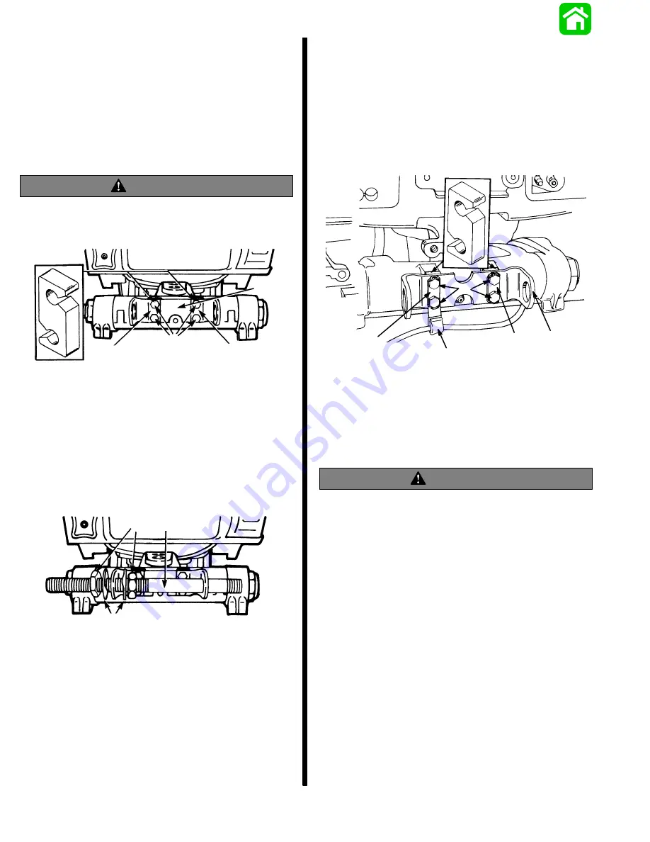
Mounting Bracket Installation
IMPORTANT:
Spacers (d) must be installed between
engine and mounting bracket.
1. Install mounting bracket (a) to engine with 2
spacers (d), 2 locking retainers (b) and 4 bolts (c).
Torque bolts to 100 lb. in. (11.3 N·m) and bend
end of locking retainers up and against flat on
each bolt, as shown.
WARNING
The locking retainer ends must be bent up and
against flat on each bolt, that secures mounting
bracket engine, to prevent bolts from turning out.
16958
a
b
c
d
b
2. Install steering cable mounting tube (a) into
mounting bracket with 2 adjustment nuts (c) and
locking tab washer (b), as shown. Be sure that
longer, threaded end of tube is toward steering
cable attaching nut side of engine.
3. Temporarily adjust tube so that longer, threaded
end of tube is extended out the same distance as
engine tilt tube. Do not tighten adjustment nuts at
this time.
16959
a
b
c
Steering Cable Mounting Tube
Installation
IMPORTANT: Spacers (b) must be installed be-
tween outboard swivel bracket and mounting
bracket for steering cable mounting tube to pro-
vide proper spacing between steering cables.
Secure mounting bracket for steering cable mounting
tube on to swivel bracket of outboard.
51891
a
b
c
d
e
d
a - Mounting Bracket for Steering Cable Mounting Tube
b - Spacer (2)
c - “J” Clip (Supplied with Outboard.)
d - Locking Retainer (2)
e - Bolts (4) - 7/8 in. (22.2mm) Long - Torque to 100 lb. in.
(11.3 N
m), then Bend Corner Tabs of Locking Retainers Up
and Against Flats on Each Bolt.
WARNING
Locking retainer corner tabs, MUST BE bent up
and against flats on each bolt that secures
mounting bracket for steering cable mounting
tube to outboard swivel bracket, to prevent bolts
from turning out.
COUPLER INSTALLATION
Install steering cable mounting tube into mounting
bracket with 2 adjusting nuts and 2 locking tab wash-
ers. Verify longer threaded end of tube is toward star-
board side of boat.
Summary of Contents for 100
Page 4: ...GENERAL INFORMATION AND SPECIFICATIONS 1 ...
Page 18: ...IGNITION SYSTEM ELECTRICAL AND IGNITION A 2 ...
Page 30: ...11669 BATTERY CHARGING SYSTEM AND STARTING SYSTEM ELECTRICAL AND IGNITION B 2 ...
Page 58: ...22480 TIMING SYNCHRONIZING ADJUSTING ELECTRICAL AND IGNITION C 2 ...
Page 71: ...WIRING DIAGRAMS ELECTRICAL AND IGNITION D 2 ...
Page 86: ...FUEL SYSTEM AND CARBURETION A 3 ...
Page 118: ...OIL INJECTION SYSTEM B 3 ...
Page 127: ...20032 3 CYLINDER ENGINES POWERHEAD A 4 ...
Page 168: ...791 H GEAR HOUSING LOWER UNIT A 5 ...
Page 170: ...5A 1 90 13645 2 1095 LOWER UNIT Notes ...
Page 205: ...MID SECTION LOWER UNIT B 5 ...
Page 207: ...5B 1 90 13645 2 495 LOWER UNIT Notes ...
Page 218: ...SHOCK ABSORBER LOWER UNIT C 5 ...
Page 223: ...17250 DESIGN I SIDE FILL RESERVOIR POWER TRIM A 6 ...
Page 233: ...6A 9 POWER TRIM 90 13645 2 495 Commander Side Mount Remote Control Wiring Diagram ...
Page 268: ...DESIGN II AFT FILL RESERVOIR POWER TRIM B 6 51344 ...
Page 305: ...SINGLE RAM POWER TRIM C 6 51485 ...
Page 309: ...6C 3 90 13645 2 495 POWER TRIM Notes ...
Page 340: ...50099 ENGINE ATTACHMENTS ENGINE INSTALLATION 7 A ...
Page 369: ...TILLER HANDLE AND CO PILOT OUTBOARD MOTOR INSTALLATION ATTACHMENTS 7 B ...
Page 371: ...7B 1 90 13645 2 495 OUTBOARD MOTOR INSTALLATION ATTACHMENTS Notes ...