


90-13645--2
1095
5A-35
LOWER UNIT
NOTE: If, while performing Step 11, the drive shaft
splines will not align with the crankshaft splines, place
a propeller onto propeller shaft and turn it counter-
clockwise as the gear housing is being pushed to-
ward drive shaft housing.
NOTE: During installation of gear housing, it may be
necessary to move the shift block (located under
cowl) slightly to align upper shift shaft splines with
shift shaft coupler splines.
11. Position gear housing so that the driveshaft is pro-
truding into drive shaft housing.
12. Move gear housing up toward drive shaft housing,
while aligning upper shift shaft splines with shift
shaft coupler splines, water tube with water tube
seal, and crank shaft splines with drive shaft
splines.
13. Install 4 bolts and washers (two each side).
14. Install locknut and washer.
15. Torque bolts and locknut (or nuts only if applica-
ble) to 40 lbs. ft. (54 N·m).
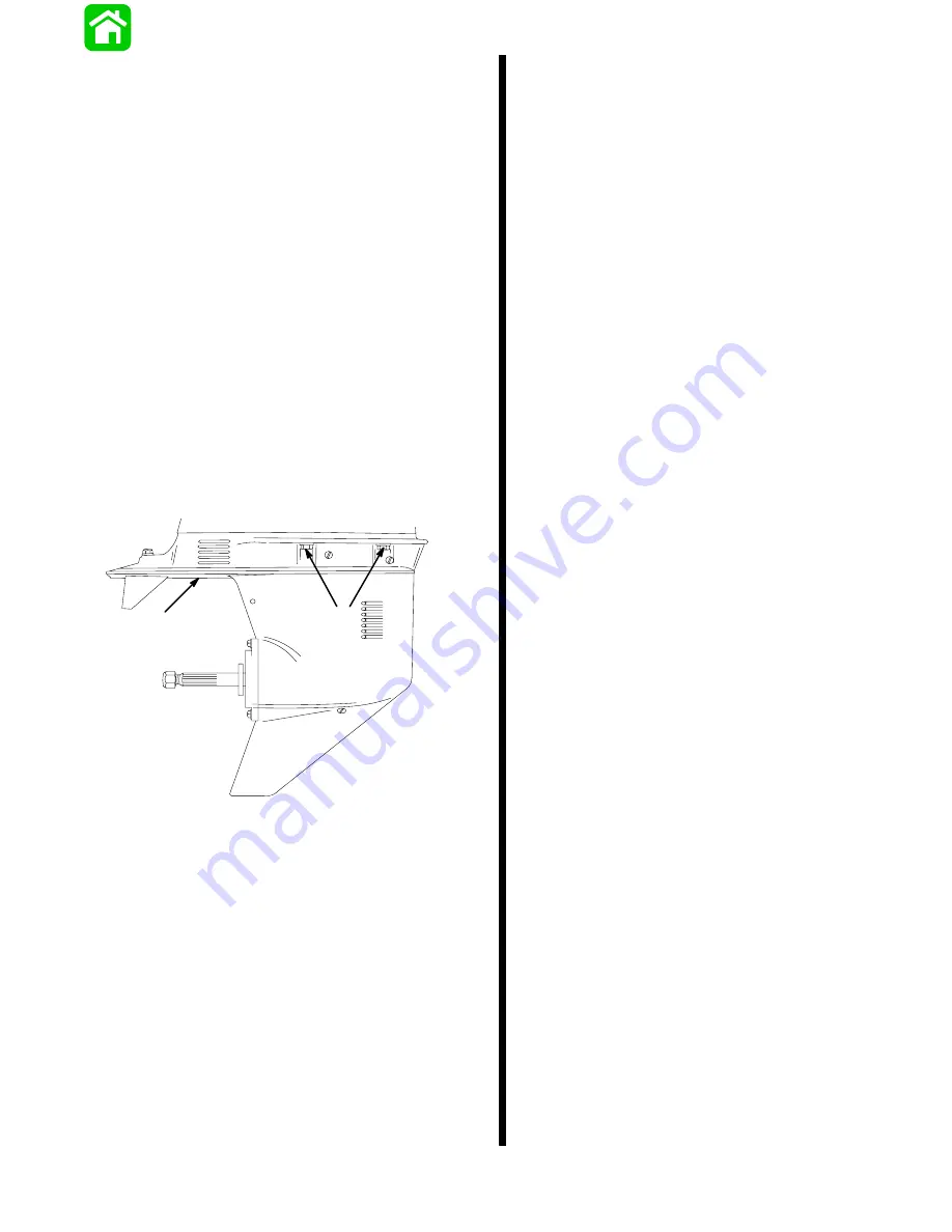
51552
a
b
a - Bolts and Washers (4)
b - Locknut and Washer
16. Check shift operation as follows:
a. Place shift lever in forward gear. Gear housing
should ratchet when propeller shaft is turned
clockwise and resistance should be felt when
propeller shaft is turned counterclockwise.
b. Place shift lever in neutral. Propeller shaft
should rotate freely in either direction.
c. While rotating propeller shaft, place shift lever
in reverse gear. Resistance should be felt when
propeller shaft is rotated in either direction.
IMPORTANT: If shift operation is not as described,
preceding, the gear housing must be removed
and the cause corrected.
Summary of Contents for 100
Page 4: ...GENERAL INFORMATION AND SPECIFICATIONS 1 ...
Page 18: ...IGNITION SYSTEM ELECTRICAL AND IGNITION A 2 ...
Page 30: ...11669 BATTERY CHARGING SYSTEM AND STARTING SYSTEM ELECTRICAL AND IGNITION B 2 ...
Page 58: ...22480 TIMING SYNCHRONIZING ADJUSTING ELECTRICAL AND IGNITION C 2 ...
Page 71: ...WIRING DIAGRAMS ELECTRICAL AND IGNITION D 2 ...
Page 86: ...FUEL SYSTEM AND CARBURETION A 3 ...
Page 118: ...OIL INJECTION SYSTEM B 3 ...
Page 127: ...20032 3 CYLINDER ENGINES POWERHEAD A 4 ...
Page 168: ...791 H GEAR HOUSING LOWER UNIT A 5 ...
Page 170: ...5A 1 90 13645 2 1095 LOWER UNIT Notes ...
Page 205: ...MID SECTION LOWER UNIT B 5 ...
Page 207: ...5B 1 90 13645 2 495 LOWER UNIT Notes ...
Page 218: ...SHOCK ABSORBER LOWER UNIT C 5 ...
Page 223: ...17250 DESIGN I SIDE FILL RESERVOIR POWER TRIM A 6 ...
Page 233: ...6A 9 POWER TRIM 90 13645 2 495 Commander Side Mount Remote Control Wiring Diagram ...
Page 268: ...DESIGN II AFT FILL RESERVOIR POWER TRIM B 6 51344 ...
Page 305: ...SINGLE RAM POWER TRIM C 6 51485 ...
Page 309: ...6C 3 90 13645 2 495 POWER TRIM Notes ...
Page 340: ...50099 ENGINE ATTACHMENTS ENGINE INSTALLATION 7 A ...
Page 369: ...TILLER HANDLE AND CO PILOT OUTBOARD MOTOR INSTALLATION ATTACHMENTS 7 B ...
Page 371: ...7B 1 90 13645 2 495 OUTBOARD MOTOR INSTALLATION ATTACHMENTS Notes ...