


5A-34
LOWER UNIT
90-13645--2
1095
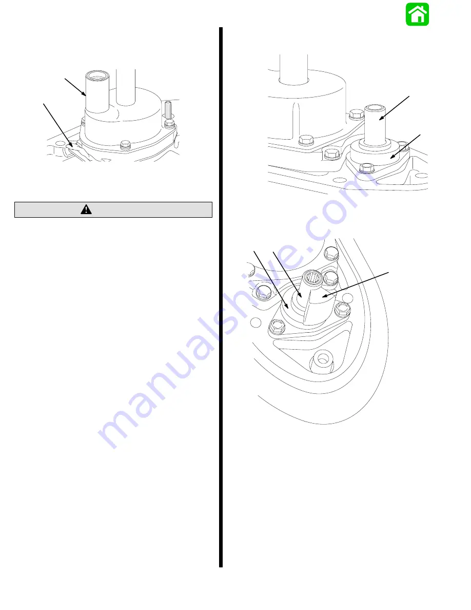
4. Install water tube seal; lube I.D. of seal with Quick-
silver 2-4-C w/Teflon (92-825407A12).
5. Apply a bead of RTV Sealer as shown.
19215
a
b
a - Water Tube Seal
b - RTV Sealer
Do not use lubricant on top of drive shaft. Excess
lubricant, that is trapped in clearance space, will
not allow drive shaft to fully engage with
crankshaft. Subsequently, tightening the gear
housing fasteners (while lubricant is on top of
drive shaft) will load the drive shaft/crankshaft
and damage either or both the power head and
gear housing. Top of drive shaft is to be wiped free
of lubricant.
CAUTION
6. Apply a light coat of Quicksilver 2-4-C w/Teflon
onto drive shaft splines.
7. Apply a light coat of Quicksilver 2-4-C w/Teflon on
gear case shift shaft splines and upper shift shaft
splines. Do not use lubricant on ends of shift
shafts.
8. Install components as shown in appropriate
photo.
19883
a
b
a - Nylon Spacer
b - Shift Shaft Coupler; Used on Models Equipped with Power
Trim
19221
a
b
c
a - Nylon Spacer
b - Shift Shaft Coupler; Used on Models NOT Equipped with
Power Trim
c - Flat; MUST BE Positioned Toward Front of Gear Housing.
9. Shift gear housing into forward gear position. In
forward gear the gear housing will ratchet when
propeller shaft is turned clockwise and resistance
will be felt when propeller shaft is rotated counter-
clockwise.
10. Apply Loctite Grade 271 on threads of gear hous-
ing retaining bolts.
Summary of Contents for 100
Page 4: ...GENERAL INFORMATION AND SPECIFICATIONS 1 ...
Page 18: ...IGNITION SYSTEM ELECTRICAL AND IGNITION A 2 ...
Page 30: ...11669 BATTERY CHARGING SYSTEM AND STARTING SYSTEM ELECTRICAL AND IGNITION B 2 ...
Page 58: ...22480 TIMING SYNCHRONIZING ADJUSTING ELECTRICAL AND IGNITION C 2 ...
Page 71: ...WIRING DIAGRAMS ELECTRICAL AND IGNITION D 2 ...
Page 86: ...FUEL SYSTEM AND CARBURETION A 3 ...
Page 118: ...OIL INJECTION SYSTEM B 3 ...
Page 127: ...20032 3 CYLINDER ENGINES POWERHEAD A 4 ...
Page 168: ...791 H GEAR HOUSING LOWER UNIT A 5 ...
Page 170: ...5A 1 90 13645 2 1095 LOWER UNIT Notes ...
Page 205: ...MID SECTION LOWER UNIT B 5 ...
Page 207: ...5B 1 90 13645 2 495 LOWER UNIT Notes ...
Page 218: ...SHOCK ABSORBER LOWER UNIT C 5 ...
Page 223: ...17250 DESIGN I SIDE FILL RESERVOIR POWER TRIM A 6 ...
Page 233: ...6A 9 POWER TRIM 90 13645 2 495 Commander Side Mount Remote Control Wiring Diagram ...
Page 268: ...DESIGN II AFT FILL RESERVOIR POWER TRIM B 6 51344 ...
Page 305: ...SINGLE RAM POWER TRIM C 6 51485 ...
Page 309: ...6C 3 90 13645 2 495 POWER TRIM Notes ...
Page 340: ...50099 ENGINE ATTACHMENTS ENGINE INSTALLATION 7 A ...
Page 369: ...TILLER HANDLE AND CO PILOT OUTBOARD MOTOR INSTALLATION ATTACHMENTS 7 B ...
Page 371: ...7B 1 90 13645 2 495 OUTBOARD MOTOR INSTALLATION ATTACHMENTS Notes ...