


4A-29
90-13645--2
495
POWERHEAD
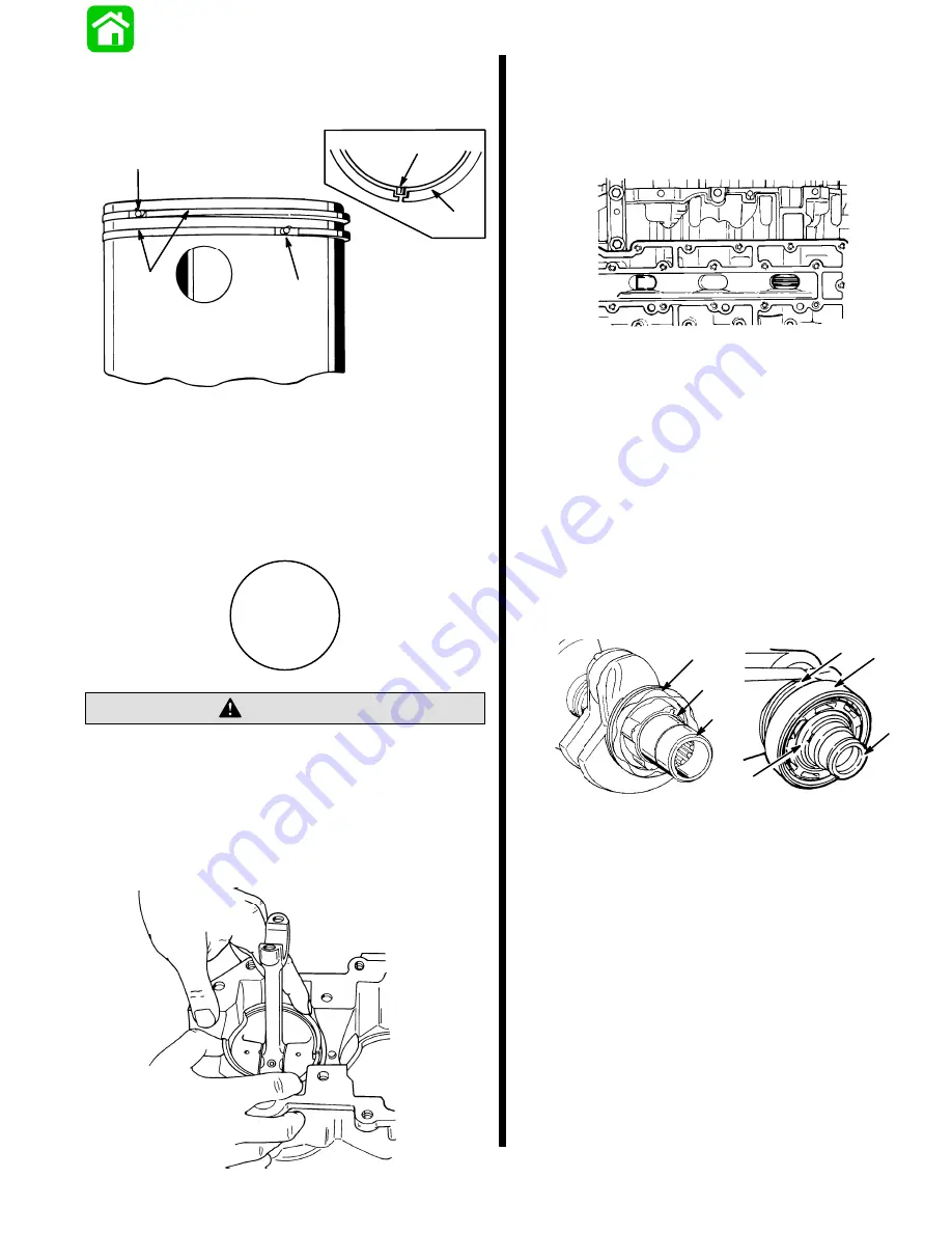
3. Align piston ring end gaps with ring locating pins
as shown. Check locating pins making sure they
are tight.
51082
a
b
51228
b
a
a
a - Locating Pin
b - Piston Rings
4. Remove connecting rod cap from connecting rod
being installed.
5. Install each piston with “UP” identification facing
flywheel end. Pistons MUST be installed in this
direction.
UP
Pistons must be installed very carefully into
cylinders. Piston rings can not be inspected thru
exhaust ports.
CAUTION
6. Bottom end of cylinder bore has taper which
permits the insertion of the piston into block
without using a piston ring compressor. Place
piston carefully into cylinder.
51087
Check rings by viewing through exhaust ports while
depressing rings with a screwdriver. If no spring ten-
sion is there (ring fails to “spring” back), the ring is
probably broken and must be replaced, NOW, before
installing the crankshaft.
20338
Crankshaft Installation
If Lower Bearing and Gear were removed from
crankshaft, reassemble using arbor press and
suitable mandrel for bearing; gear slides on.
(NOTE keyway and key in gear to crankshaft
assembly.)
Install main bearing retaining ring after pressing
main bearing tight against the oil gear.
NOTE: There is NO main bearing retaining ring or re-
taining ring groove in the crankshaft on the following
outboards:
25949
51084
a
b
c
d
e
75/90–SERIAL NUMBER OC 259434 and above.
b
d
a - Lower Bearing
b - Gear
c - Retaining Ring
d - Seal Carrier
e - Key
If Seal Carrier above was removed, replace by
placing a piece of wood on carrier and tapping
gently with a mallet, keeping carrier “square” dur-
ing insertion, seal fully to crankshaft. See page
4A-17 -- (Powerhead Disassembly, this Section),
for wear-sleeve reinstallation, if so equipped.
Summary of Contents for 100
Page 4: ...GENERAL INFORMATION AND SPECIFICATIONS 1 ...
Page 18: ...IGNITION SYSTEM ELECTRICAL AND IGNITION A 2 ...
Page 30: ...11669 BATTERY CHARGING SYSTEM AND STARTING SYSTEM ELECTRICAL AND IGNITION B 2 ...
Page 58: ...22480 TIMING SYNCHRONIZING ADJUSTING ELECTRICAL AND IGNITION C 2 ...
Page 71: ...WIRING DIAGRAMS ELECTRICAL AND IGNITION D 2 ...
Page 86: ...FUEL SYSTEM AND CARBURETION A 3 ...
Page 118: ...OIL INJECTION SYSTEM B 3 ...
Page 127: ...20032 3 CYLINDER ENGINES POWERHEAD A 4 ...
Page 168: ...791 H GEAR HOUSING LOWER UNIT A 5 ...
Page 170: ...5A 1 90 13645 2 1095 LOWER UNIT Notes ...
Page 205: ...MID SECTION LOWER UNIT B 5 ...
Page 207: ...5B 1 90 13645 2 495 LOWER UNIT Notes ...
Page 218: ...SHOCK ABSORBER LOWER UNIT C 5 ...
Page 223: ...17250 DESIGN I SIDE FILL RESERVOIR POWER TRIM A 6 ...
Page 233: ...6A 9 POWER TRIM 90 13645 2 495 Commander Side Mount Remote Control Wiring Diagram ...
Page 268: ...DESIGN II AFT FILL RESERVOIR POWER TRIM B 6 51344 ...
Page 305: ...SINGLE RAM POWER TRIM C 6 51485 ...
Page 309: ...6C 3 90 13645 2 495 POWER TRIM Notes ...
Page 340: ...50099 ENGINE ATTACHMENTS ENGINE INSTALLATION 7 A ...
Page 369: ...TILLER HANDLE AND CO PILOT OUTBOARD MOTOR INSTALLATION ATTACHMENTS 7 B ...
Page 371: ...7B 1 90 13645 2 495 OUTBOARD MOTOR INSTALLATION ATTACHMENTS Notes ...