


6C-2
90-13645--2
495
POWER-TRIM
Improves planing speed acceleration (by moving tilt
bolt one hole closer to transom).
Operating “Down” circuit will actuate the “down” relay
(located under engine cowl) and close the electric
motor circuit (motor will run in opposite direction of the
“Up” circuit). The electric motor will drive the pump,
forcing fluid thru internal passageways into the
“down” side of the tilt ram. The tilt ram will move the
engine down to the desired angle.
Trailering Outboard
WARNING
Excessive engine trim angle will result in
insufficient water supply to water pump causing
water pump and/or powerhead overheating
damage. Make sure that water level is above gear
housing water intake holes whenever engine is
running.
While operating “up” circuit, the ram will continue to tilt
outboard to full up position for trailering.
Tilting Outboard Up and Down
Manually
WARNING
Before opening the manual release valve, make
sure all persons are clear of engine as engine will
drop to full “down” position when valve is
opened.
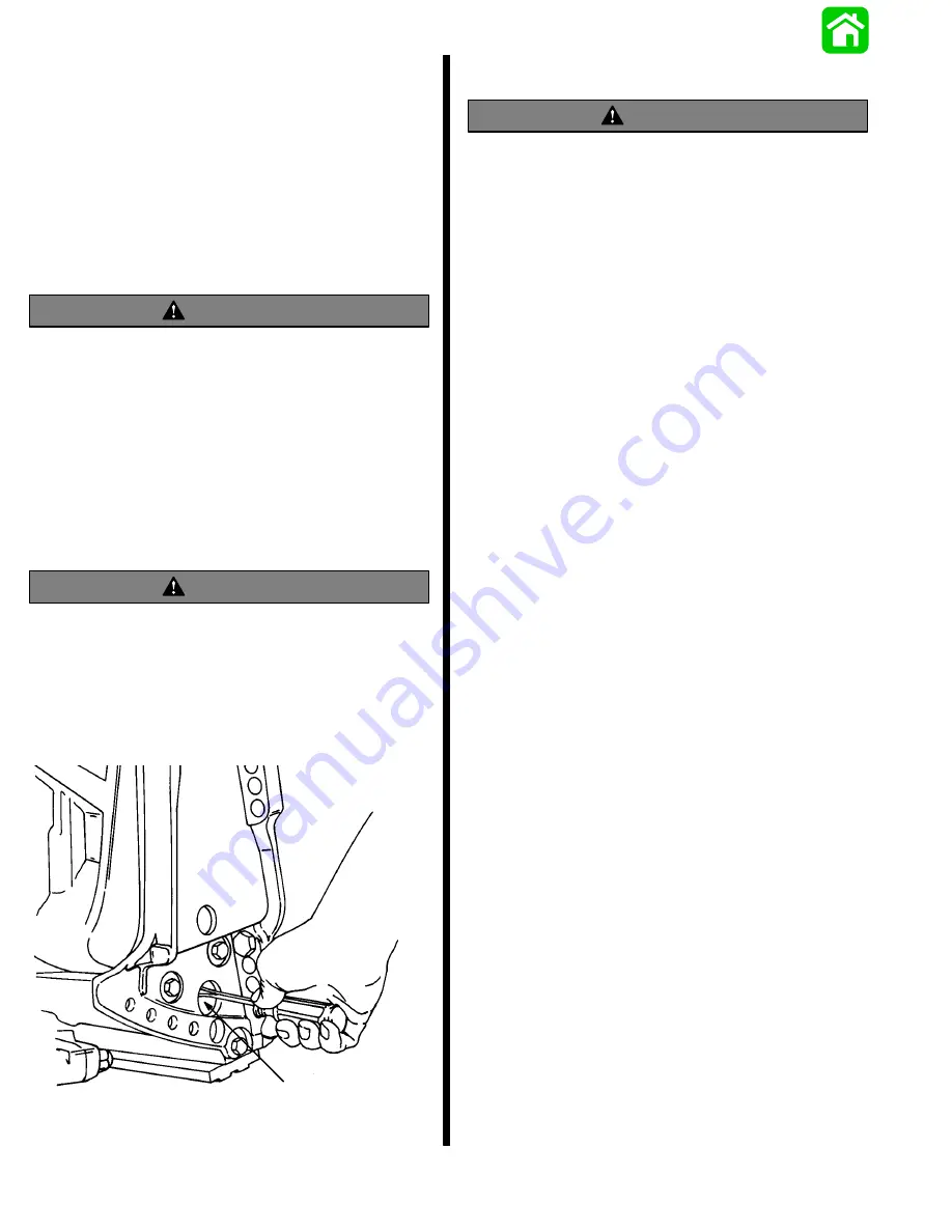
With power trim installed, the outboard can be raised
or lowered manually by opening the manual release
valve 3 turns maximum (counterclockwise).
51432
a
a - Manual Release Valve
Trim “In” Angle Adjustment
WARNING
Operating some boats with engine trimmed to the
full “in” trim angle [not using trim adjustment bolt]
at planing speed will cause undesirable and/or
unsafe steering conditions. Each boat must be
water tested for handling characteristics after
engine installation and after any trim
adjustments.
IMPORTANT: Some boat/motor combinations,
that do not use the trim adjustment bolt and are
trimmed to the full “in” trim angle, will not experi-
ence any undesirable and/or unsafe steering con-
ditions during planing speed. Thus, not using trim
adjustment bolt may be desired. However, some
boats with engine trimmed to the full “in” trim
angle at planing speed will cause undesirable
and/or unsafe steering conditions. If these steer-
ing conditions are experienced, under no circum-
stances should the engine be operated without
the trim adjustment bolt and without the bolt ad-
justed in the proper holes to prevent unsafe han-
dling characteristics.
Water test the boat not using the trim adjustment bolt.
If undesirable and/or unsafe steering conditions are
experienced (boat runs with nose down), install trim
adjustment bolt in proper hole to prevent unsafe han-
dling characteristics.
Summary of Contents for 100
Page 4: ...GENERAL INFORMATION AND SPECIFICATIONS 1 ...
Page 18: ...IGNITION SYSTEM ELECTRICAL AND IGNITION A 2 ...
Page 30: ...11669 BATTERY CHARGING SYSTEM AND STARTING SYSTEM ELECTRICAL AND IGNITION B 2 ...
Page 58: ...22480 TIMING SYNCHRONIZING ADJUSTING ELECTRICAL AND IGNITION C 2 ...
Page 71: ...WIRING DIAGRAMS ELECTRICAL AND IGNITION D 2 ...
Page 86: ...FUEL SYSTEM AND CARBURETION A 3 ...
Page 118: ...OIL INJECTION SYSTEM B 3 ...
Page 127: ...20032 3 CYLINDER ENGINES POWERHEAD A 4 ...
Page 168: ...791 H GEAR HOUSING LOWER UNIT A 5 ...
Page 170: ...5A 1 90 13645 2 1095 LOWER UNIT Notes ...
Page 205: ...MID SECTION LOWER UNIT B 5 ...
Page 207: ...5B 1 90 13645 2 495 LOWER UNIT Notes ...
Page 218: ...SHOCK ABSORBER LOWER UNIT C 5 ...
Page 223: ...17250 DESIGN I SIDE FILL RESERVOIR POWER TRIM A 6 ...
Page 233: ...6A 9 POWER TRIM 90 13645 2 495 Commander Side Mount Remote Control Wiring Diagram ...
Page 268: ...DESIGN II AFT FILL RESERVOIR POWER TRIM B 6 51344 ...
Page 305: ...SINGLE RAM POWER TRIM C 6 51485 ...
Page 309: ...6C 3 90 13645 2 495 POWER TRIM Notes ...
Page 340: ...50099 ENGINE ATTACHMENTS ENGINE INSTALLATION 7 A ...
Page 369: ...TILLER HANDLE AND CO PILOT OUTBOARD MOTOR INSTALLATION ATTACHMENTS 7 B ...
Page 371: ...7B 1 90 13645 2 495 OUTBOARD MOTOR INSTALLATION ATTACHMENTS Notes ...