


6A-29
POWER TRIM
90-13645--2
495
Tilt Ram
REMOVAL
1. Remove Power Trim assembly from engine, refer
to “Removal” instructions in “Power Trim Assem-
bly Removal and Installation,” preceding.
Slowly remove fill screw to bleed pressure from
reservoir.
From a full closed (clockwise) position, slowly
open manual release valve 3 to 4 turns (counter-
clockwise) to bleed remaining pressure from
Power Trim system.
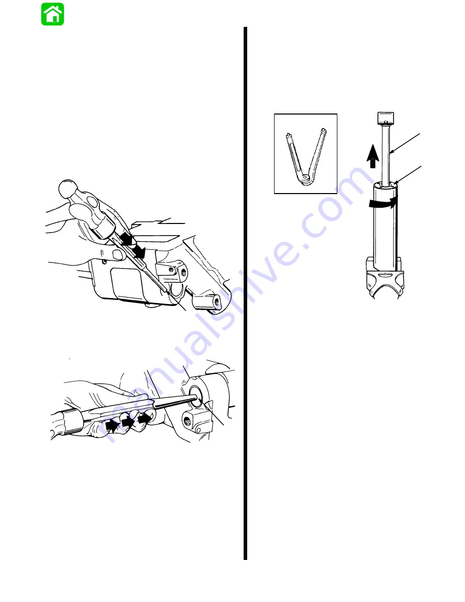
Remove pin by driving pin in direction shown.
51366
a
a - Pin
2. Remove shaft by driving shaft in direction shown.
51355
a
a - Shaft
DISASSEMBLY
1. Secure tilt ram (at its base) in a soft jawed vise.
Using Spanner Wrench, loosen cap by turning
cap in direction.
Remove ram from vise, and pour fluid from ram.
Pull rod assembly out of ram.
51364
91-74951
51337
a
b
c
d
a - Spanner Wrench
b - Cap
c - Turn in Counterclockwise Direction
d - Rod Assembly
Summary of Contents for 100
Page 4: ...GENERAL INFORMATION AND SPECIFICATIONS 1 ...
Page 18: ...IGNITION SYSTEM ELECTRICAL AND IGNITION A 2 ...
Page 30: ...11669 BATTERY CHARGING SYSTEM AND STARTING SYSTEM ELECTRICAL AND IGNITION B 2 ...
Page 58: ...22480 TIMING SYNCHRONIZING ADJUSTING ELECTRICAL AND IGNITION C 2 ...
Page 71: ...WIRING DIAGRAMS ELECTRICAL AND IGNITION D 2 ...
Page 86: ...FUEL SYSTEM AND CARBURETION A 3 ...
Page 118: ...OIL INJECTION SYSTEM B 3 ...
Page 127: ...20032 3 CYLINDER ENGINES POWERHEAD A 4 ...
Page 168: ...791 H GEAR HOUSING LOWER UNIT A 5 ...
Page 170: ...5A 1 90 13645 2 1095 LOWER UNIT Notes ...
Page 205: ...MID SECTION LOWER UNIT B 5 ...
Page 207: ...5B 1 90 13645 2 495 LOWER UNIT Notes ...
Page 218: ...SHOCK ABSORBER LOWER UNIT C 5 ...
Page 223: ...17250 DESIGN I SIDE FILL RESERVOIR POWER TRIM A 6 ...
Page 233: ...6A 9 POWER TRIM 90 13645 2 495 Commander Side Mount Remote Control Wiring Diagram ...
Page 268: ...DESIGN II AFT FILL RESERVOIR POWER TRIM B 6 51344 ...
Page 305: ...SINGLE RAM POWER TRIM C 6 51485 ...
Page 309: ...6C 3 90 13645 2 495 POWER TRIM Notes ...
Page 340: ...50099 ENGINE ATTACHMENTS ENGINE INSTALLATION 7 A ...
Page 369: ...TILLER HANDLE AND CO PILOT OUTBOARD MOTOR INSTALLATION ATTACHMENTS 7 B ...
Page 371: ...7B 1 90 13645 2 495 OUTBOARD MOTOR INSTALLATION ATTACHMENTS Notes ...