


4A-35
90-13645--2
495
POWERHEAD
Powerhead to Driveshaft Housing
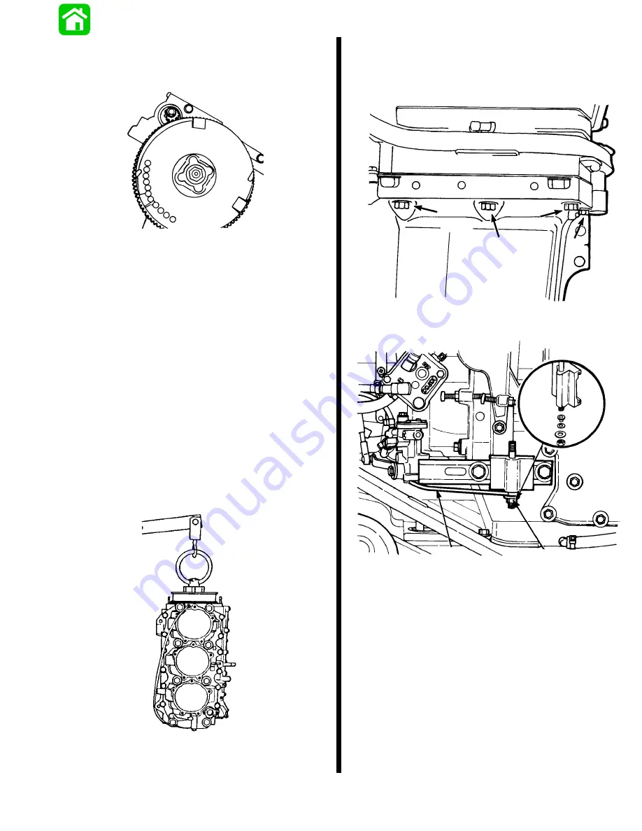
Temporarily install flywheel with nut, as shown.
20346
Install lifting eye (91-90455) onto flywheel. Thread
on at least 5 full turns.
After checking mating surfaces between power-
head and driveshaft housing for condition and
cleanliness, use hoist to lift powerhead, being
careful not to damage powerhead to driveshaft
housing gasket surface.
Place new gasket over locating pins on driveshaft
housing-to-powerhead mating surface.
Apply a small amount of Quicksilver 2-4-C w/Te-
flon to driveshaft splines.
Recheck for correct installation of tip-seal in crank-
shaft seal carrier.
Use hoist to lower powerhead into driveshaft
housing, turning flywheel, if necessary, to align
crankshaft splines with driveshaft splines. Lower
so that powerhead is fully installed and aligned on
locating pins.
20031
Clean holes (threads) and bolts thoroughly, with Loc-
quic Primer T (92-59327-1). Dry, apply Loctite 271 to
bolts, and install. There are 8 bolts (3 each side, 2
backside). Torque in 3 Steps to 45 lb. ft. (61.0 N
m).
19070
Reattach shift arm linkage on stud.
19544
a
b
a - Shift Arm Linkage
b - Stud
NOTE: For specific information on rewiring, see Sec-
tion 4-D, “Wiring Diagrams” (this manual).
Summary of Contents for 100
Page 4: ...GENERAL INFORMATION AND SPECIFICATIONS 1 ...
Page 18: ...IGNITION SYSTEM ELECTRICAL AND IGNITION A 2 ...
Page 30: ...11669 BATTERY CHARGING SYSTEM AND STARTING SYSTEM ELECTRICAL AND IGNITION B 2 ...
Page 58: ...22480 TIMING SYNCHRONIZING ADJUSTING ELECTRICAL AND IGNITION C 2 ...
Page 71: ...WIRING DIAGRAMS ELECTRICAL AND IGNITION D 2 ...
Page 86: ...FUEL SYSTEM AND CARBURETION A 3 ...
Page 118: ...OIL INJECTION SYSTEM B 3 ...
Page 127: ...20032 3 CYLINDER ENGINES POWERHEAD A 4 ...
Page 168: ...791 H GEAR HOUSING LOWER UNIT A 5 ...
Page 170: ...5A 1 90 13645 2 1095 LOWER UNIT Notes ...
Page 205: ...MID SECTION LOWER UNIT B 5 ...
Page 207: ...5B 1 90 13645 2 495 LOWER UNIT Notes ...
Page 218: ...SHOCK ABSORBER LOWER UNIT C 5 ...
Page 223: ...17250 DESIGN I SIDE FILL RESERVOIR POWER TRIM A 6 ...
Page 233: ...6A 9 POWER TRIM 90 13645 2 495 Commander Side Mount Remote Control Wiring Diagram ...
Page 268: ...DESIGN II AFT FILL RESERVOIR POWER TRIM B 6 51344 ...
Page 305: ...SINGLE RAM POWER TRIM C 6 51485 ...
Page 309: ...6C 3 90 13645 2 495 POWER TRIM Notes ...
Page 340: ...50099 ENGINE ATTACHMENTS ENGINE INSTALLATION 7 A ...
Page 369: ...TILLER HANDLE AND CO PILOT OUTBOARD MOTOR INSTALLATION ATTACHMENTS 7 B ...
Page 371: ...7B 1 90 13645 2 495 OUTBOARD MOTOR INSTALLATION ATTACHMENTS Notes ...