


6A-27
POWER TRIM
90-13645--2
495
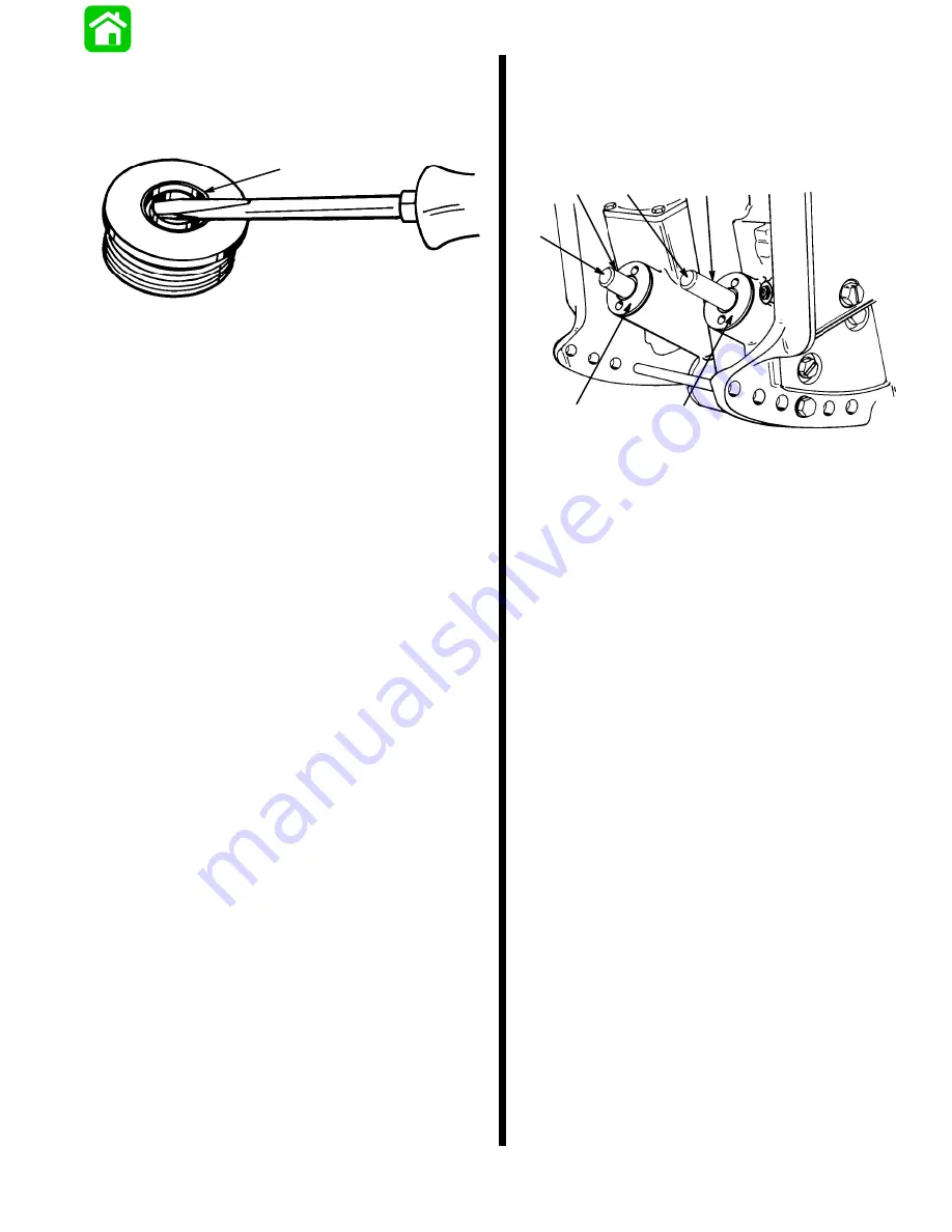
Trim Rod End Cap Seal
1. Inspect trim cap end seal and replace if damaged
or if seal does not keep trim rod clean.
51343
a
a - Seal (Remove as shown)
2. Install new seal with seal lip up.
TRIM ROD INSTALLATION
IMPORTANT: Components must be free of dirt and
lint. Any debris in the system can cause system
to malfunction.
NOTE: Install trim rod with check valve in the port (left)
cylinder.
1. Apply Quicksilver Power Trim and Steering Fluid
on all O-rings and seals before installation.
2. Install trim rods and caps. Use Installation Tool
(91-44487A1) or Spanner Wrench (91-74951) to
tighten caps securely.
51353
a
a
b
b
c
c
a -
Trim Rods
b -
Cylinder End Caps
c -
Rod End Rollers (lubricate with Quicksilver Anti-Corrosion Grease or
2-4-C w/Teflon)
Summary of Contents for 100
Page 4: ...GENERAL INFORMATION AND SPECIFICATIONS 1 ...
Page 18: ...IGNITION SYSTEM ELECTRICAL AND IGNITION A 2 ...
Page 30: ...11669 BATTERY CHARGING SYSTEM AND STARTING SYSTEM ELECTRICAL AND IGNITION B 2 ...
Page 58: ...22480 TIMING SYNCHRONIZING ADJUSTING ELECTRICAL AND IGNITION C 2 ...
Page 71: ...WIRING DIAGRAMS ELECTRICAL AND IGNITION D 2 ...
Page 86: ...FUEL SYSTEM AND CARBURETION A 3 ...
Page 118: ...OIL INJECTION SYSTEM B 3 ...
Page 127: ...20032 3 CYLINDER ENGINES POWERHEAD A 4 ...
Page 168: ...791 H GEAR HOUSING LOWER UNIT A 5 ...
Page 170: ...5A 1 90 13645 2 1095 LOWER UNIT Notes ...
Page 205: ...MID SECTION LOWER UNIT B 5 ...
Page 207: ...5B 1 90 13645 2 495 LOWER UNIT Notes ...
Page 218: ...SHOCK ABSORBER LOWER UNIT C 5 ...
Page 223: ...17250 DESIGN I SIDE FILL RESERVOIR POWER TRIM A 6 ...
Page 233: ...6A 9 POWER TRIM 90 13645 2 495 Commander Side Mount Remote Control Wiring Diagram ...
Page 268: ...DESIGN II AFT FILL RESERVOIR POWER TRIM B 6 51344 ...
Page 305: ...SINGLE RAM POWER TRIM C 6 51485 ...
Page 309: ...6C 3 90 13645 2 495 POWER TRIM Notes ...
Page 340: ...50099 ENGINE ATTACHMENTS ENGINE INSTALLATION 7 A ...
Page 369: ...TILLER HANDLE AND CO PILOT OUTBOARD MOTOR INSTALLATION ATTACHMENTS 7 B ...
Page 371: ...7B 1 90 13645 2 495 OUTBOARD MOTOR INSTALLATION ATTACHMENTS Notes ...