


3A-17
90-13645--2
495
FUEL SYSTEM AND CARBURETION
Carburetor Adjustments
INITIAL STARTING ADJUSTMENT
After service or replacement of carburetor, turn low
speed mixture screw adjustment in (CLOCKWISE)
until it seats LIGHTLY – then back off (each
carburetor) the number of turns per model as
indicated, following:
70 H.P. --- 1-1/4
75 H.P. --- 1-1/2
80 H.P. --- 1-1/2
90 H.P. --- 1-1/2
100 H.P. --- 1-3/4
115 H.P. --- 1-1/2
This adjustment will permit engine startup.
LOW SPEED MIXTURE ADJUSTMENT
NOTE: Only the top two carburetors on four cylinder
models have adjustable idle mixture screws.
1. Start engine and allow to warm-up (run for several
minutes). Throttle back engine to idle for about
one minute to allow RPMs to stabilize.
2. With engine running at idle speed -- in water -- IN
FORWARD GEAR (prop on) -- turn low speed
mixture screw IN (clockwise) until engine starts to
“bog” down and misfire. Back out 1/4 turn or more.
22990
a
a - Low Speed Mixture Screw
3. Check for too lean mixture on acceleration.
4. DO NOT adjust leaner than necessary to attain
reasonably smooth idling. When in doubt, stay on
the slightly rich side of the adjustment.
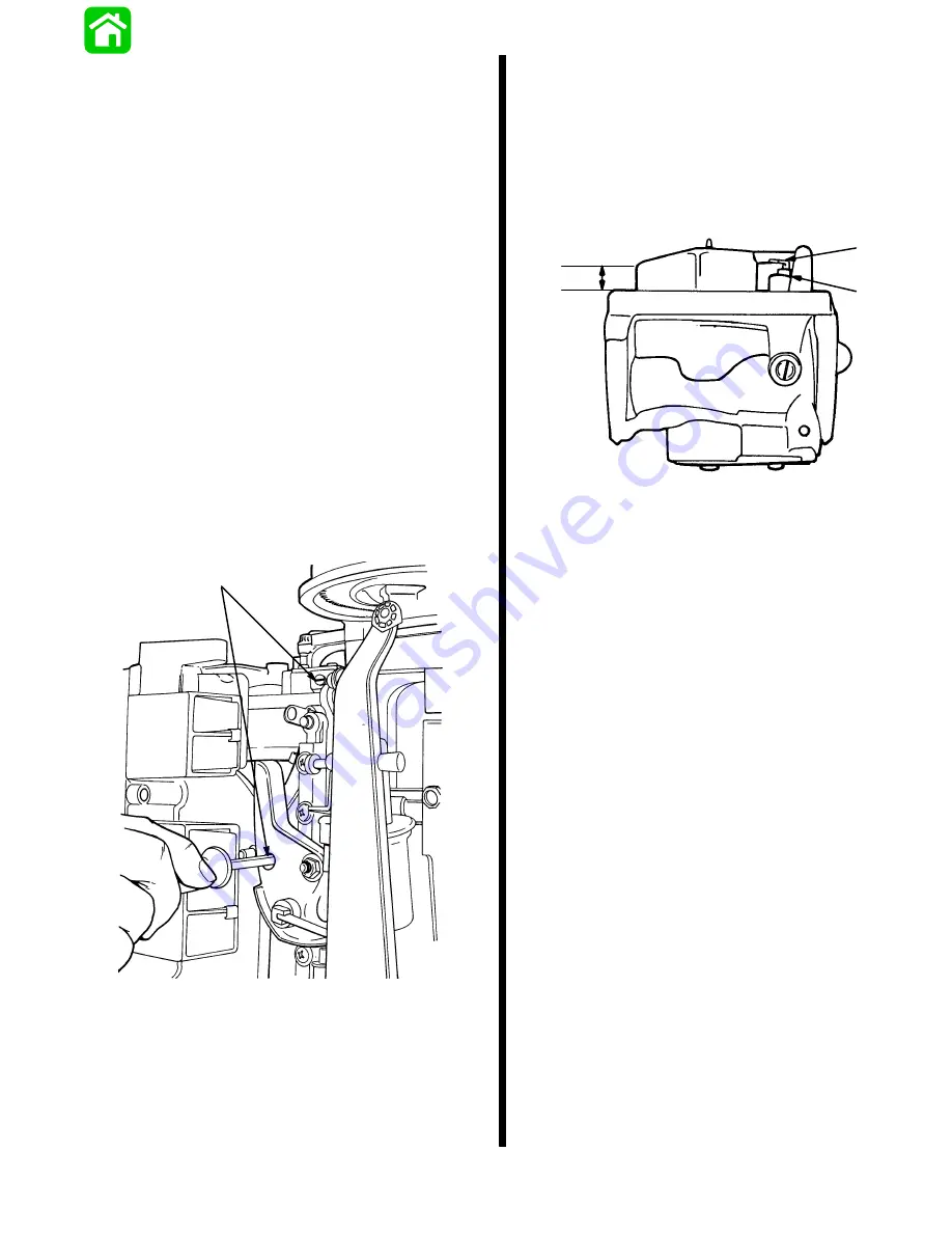
CARBURETOR FLOAT ADJUSTMENT
1. If installed, remove carburetor as outlined in
“Carburetor Removal”, following.
2. Remove fuel bowl and gasket and check float
level as shown.
3. If necessary, adjust float level by bending metal
tab on float to which inlet needle is clipped.
a
b
11.1 mm
(7/16 in.)
a - Metal Tab
b - Inlet Needle
Summary of Contents for 100
Page 4: ...GENERAL INFORMATION AND SPECIFICATIONS 1 ...
Page 18: ...IGNITION SYSTEM ELECTRICAL AND IGNITION A 2 ...
Page 30: ...11669 BATTERY CHARGING SYSTEM AND STARTING SYSTEM ELECTRICAL AND IGNITION B 2 ...
Page 58: ...22480 TIMING SYNCHRONIZING ADJUSTING ELECTRICAL AND IGNITION C 2 ...
Page 71: ...WIRING DIAGRAMS ELECTRICAL AND IGNITION D 2 ...
Page 86: ...FUEL SYSTEM AND CARBURETION A 3 ...
Page 118: ...OIL INJECTION SYSTEM B 3 ...
Page 127: ...20032 3 CYLINDER ENGINES POWERHEAD A 4 ...
Page 168: ...791 H GEAR HOUSING LOWER UNIT A 5 ...
Page 170: ...5A 1 90 13645 2 1095 LOWER UNIT Notes ...
Page 205: ...MID SECTION LOWER UNIT B 5 ...
Page 207: ...5B 1 90 13645 2 495 LOWER UNIT Notes ...
Page 218: ...SHOCK ABSORBER LOWER UNIT C 5 ...
Page 223: ...17250 DESIGN I SIDE FILL RESERVOIR POWER TRIM A 6 ...
Page 233: ...6A 9 POWER TRIM 90 13645 2 495 Commander Side Mount Remote Control Wiring Diagram ...
Page 268: ...DESIGN II AFT FILL RESERVOIR POWER TRIM B 6 51344 ...
Page 305: ...SINGLE RAM POWER TRIM C 6 51485 ...
Page 309: ...6C 3 90 13645 2 495 POWER TRIM Notes ...
Page 340: ...50099 ENGINE ATTACHMENTS ENGINE INSTALLATION 7 A ...
Page 369: ...TILLER HANDLE AND CO PILOT OUTBOARD MOTOR INSTALLATION ATTACHMENTS 7 B ...
Page 371: ...7B 1 90 13645 2 495 OUTBOARD MOTOR INSTALLATION ATTACHMENTS Notes ...