


6C-9
90-13645--2
495
POWER-TRIM
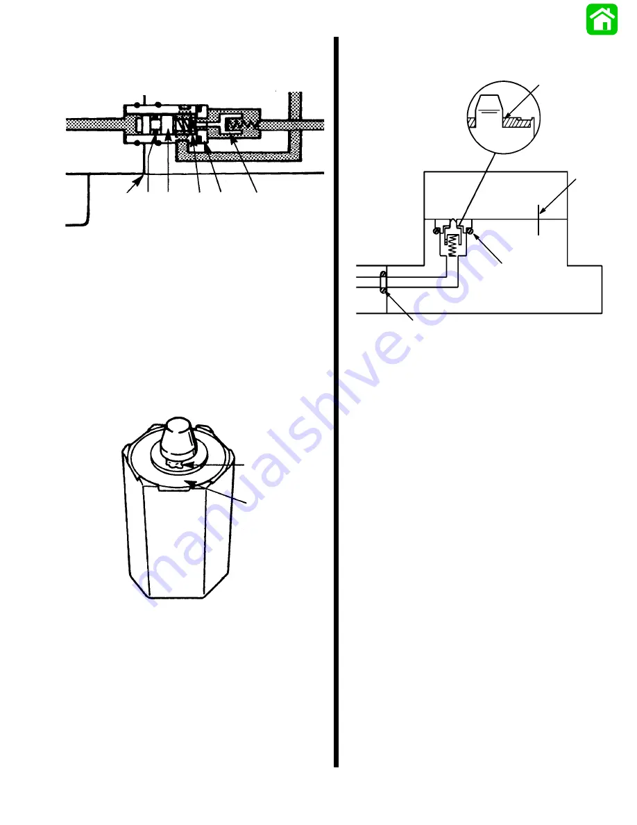
3. A leak path is created between the UP side of the
cylinder and the reservoir when the spool sticks
holding the pilot valve open.
a
b
c
d
e
f
a - Cylinder/Manifold Mating Surface
b - O-ring
c - Spool
d - Return Spring
e - Valve Seat
f - Pilot Valve Held Open (away from valve seat)
4. Power trim units with date code 23289 and higher
have improved o-rings and improved surface fin-
ish on the inside of the sleeve to correct the prob-
lem.
5. To correct a slow leak down, check for debris be-
tween the valve seat and valve.
52792
a
b
a - Chip under Valve Tip
b - Rubber Seat
6. Inspect for nicked, deteriorated, or misplaced
O-ring .
51560
a
b
c
d
a - Valve and Seat
b - O-ring
c - O-ring
d - Scribe Mark
Reassembly
1. Install the spool into sleeve from the chamfered
end (end opposite the cross hole).
2. Insert spool into sleeve until end is flush with the
chamfered end of the sleeve. Inserting the spool
too far into the sleeve may allow the spool o-ring
to contact the sharp edges of the sleeve cross
hole and damage the o-ring.
3. After reassembly, insert driveshaft and check
pump rotor resistance to turning - housing halves
can shift/turn during reassembly. Align scribe
marks carefully.
Summary of Contents for 100
Page 4: ...GENERAL INFORMATION AND SPECIFICATIONS 1 ...
Page 18: ...IGNITION SYSTEM ELECTRICAL AND IGNITION A 2 ...
Page 30: ...11669 BATTERY CHARGING SYSTEM AND STARTING SYSTEM ELECTRICAL AND IGNITION B 2 ...
Page 58: ...22480 TIMING SYNCHRONIZING ADJUSTING ELECTRICAL AND IGNITION C 2 ...
Page 71: ...WIRING DIAGRAMS ELECTRICAL AND IGNITION D 2 ...
Page 86: ...FUEL SYSTEM AND CARBURETION A 3 ...
Page 118: ...OIL INJECTION SYSTEM B 3 ...
Page 127: ...20032 3 CYLINDER ENGINES POWERHEAD A 4 ...
Page 168: ...791 H GEAR HOUSING LOWER UNIT A 5 ...
Page 170: ...5A 1 90 13645 2 1095 LOWER UNIT Notes ...
Page 205: ...MID SECTION LOWER UNIT B 5 ...
Page 207: ...5B 1 90 13645 2 495 LOWER UNIT Notes ...
Page 218: ...SHOCK ABSORBER LOWER UNIT C 5 ...
Page 223: ...17250 DESIGN I SIDE FILL RESERVOIR POWER TRIM A 6 ...
Page 233: ...6A 9 POWER TRIM 90 13645 2 495 Commander Side Mount Remote Control Wiring Diagram ...
Page 268: ...DESIGN II AFT FILL RESERVOIR POWER TRIM B 6 51344 ...
Page 305: ...SINGLE RAM POWER TRIM C 6 51485 ...
Page 309: ...6C 3 90 13645 2 495 POWER TRIM Notes ...
Page 340: ...50099 ENGINE ATTACHMENTS ENGINE INSTALLATION 7 A ...
Page 369: ...TILLER HANDLE AND CO PILOT OUTBOARD MOTOR INSTALLATION ATTACHMENTS 7 B ...
Page 371: ...7B 1 90 13645 2 495 OUTBOARD MOTOR INSTALLATION ATTACHMENTS Notes ...