


6C-17
90-13645--2
495
POWER-TRIM
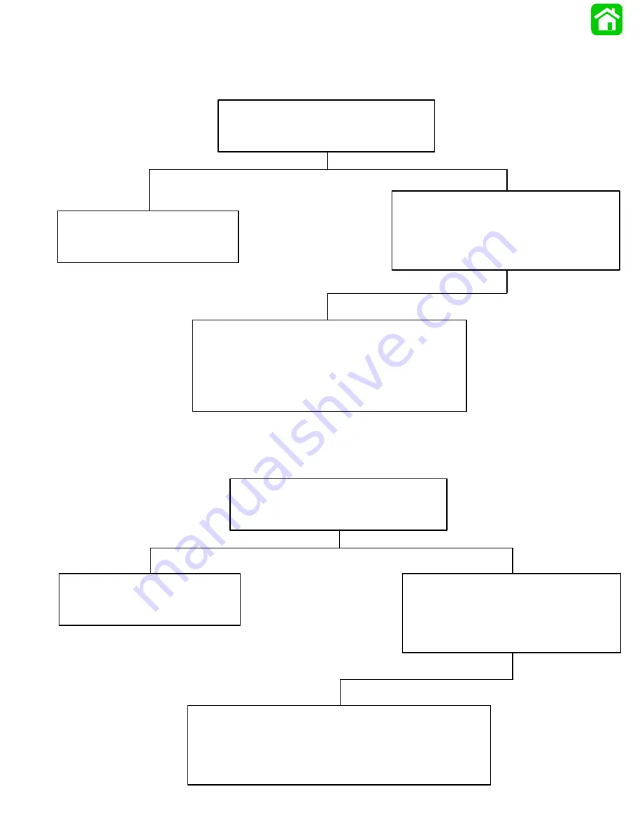
Troubleshooting the “Down” Circuit*
(When “Up” Circuit is OK)
*Remote Control Not Equipped with Trailer Button
Battery Voltage Indicated:
Down Relay is Defective. Replace
and retest.
No Voltage Indicated:
Connect Voltmeter red lead to Point 4 and
black lead to ground. Depress “Down” trim
button. If battery voltage is indicated, wire
is open between Points 4 and 1.
No Voltage Indicated:
Connect Voltmeter red lead to Point 5. If battery volt-
age is indicated, trim switch is faulty. If no battery
voltage, check for loose or corroded connection at
Point 5 or open circuit in wire supplying current to
Point 5.
Connect Voltmeter red lead to Point 1
and black lead to ground.
Depress the “Down” trim button.
Troubleshooting the “Up” Circuit*
(When “Down” Circuit Is OK)
*Remote Control NOT Equipped with Trailer Button
Battery Voltage Indicated:
UP Relay is defective. Replace
and retest.
No Voltage Indicated:
Connect Voltmeter red lead to Point 7 and
black lead to ground. Depress “Down”
trim button. If battery voltage is indicated,
wire is open between Points 7 and 8.
No Voltage Indicated:
Connect Voltmeter red lead to Point 5. If battery voltage is
indicated, trim switch is faulty. If no battery voltage, check
for loose or corroded connection at Point 5 or open circuit
in wire supplying current to Point 5.
Connect Voltmeter red lead to Point 8
and black lead to ground.
Depress the “Up” trim button.
Summary of Contents for 100
Page 4: ...GENERAL INFORMATION AND SPECIFICATIONS 1 ...
Page 18: ...IGNITION SYSTEM ELECTRICAL AND IGNITION A 2 ...
Page 30: ...11669 BATTERY CHARGING SYSTEM AND STARTING SYSTEM ELECTRICAL AND IGNITION B 2 ...
Page 58: ...22480 TIMING SYNCHRONIZING ADJUSTING ELECTRICAL AND IGNITION C 2 ...
Page 71: ...WIRING DIAGRAMS ELECTRICAL AND IGNITION D 2 ...
Page 86: ...FUEL SYSTEM AND CARBURETION A 3 ...
Page 118: ...OIL INJECTION SYSTEM B 3 ...
Page 127: ...20032 3 CYLINDER ENGINES POWERHEAD A 4 ...
Page 168: ...791 H GEAR HOUSING LOWER UNIT A 5 ...
Page 170: ...5A 1 90 13645 2 1095 LOWER UNIT Notes ...
Page 205: ...MID SECTION LOWER UNIT B 5 ...
Page 207: ...5B 1 90 13645 2 495 LOWER UNIT Notes ...
Page 218: ...SHOCK ABSORBER LOWER UNIT C 5 ...
Page 223: ...17250 DESIGN I SIDE FILL RESERVOIR POWER TRIM A 6 ...
Page 233: ...6A 9 POWER TRIM 90 13645 2 495 Commander Side Mount Remote Control Wiring Diagram ...
Page 268: ...DESIGN II AFT FILL RESERVOIR POWER TRIM B 6 51344 ...
Page 305: ...SINGLE RAM POWER TRIM C 6 51485 ...
Page 309: ...6C 3 90 13645 2 495 POWER TRIM Notes ...
Page 340: ...50099 ENGINE ATTACHMENTS ENGINE INSTALLATION 7 A ...
Page 369: ...TILLER HANDLE AND CO PILOT OUTBOARD MOTOR INSTALLATION ATTACHMENTS 7 B ...
Page 371: ...7B 1 90 13645 2 495 OUTBOARD MOTOR INSTALLATION ATTACHMENTS Notes ...