


7A-24
ENGINE ATTACHMENTS
90-13645--2
495
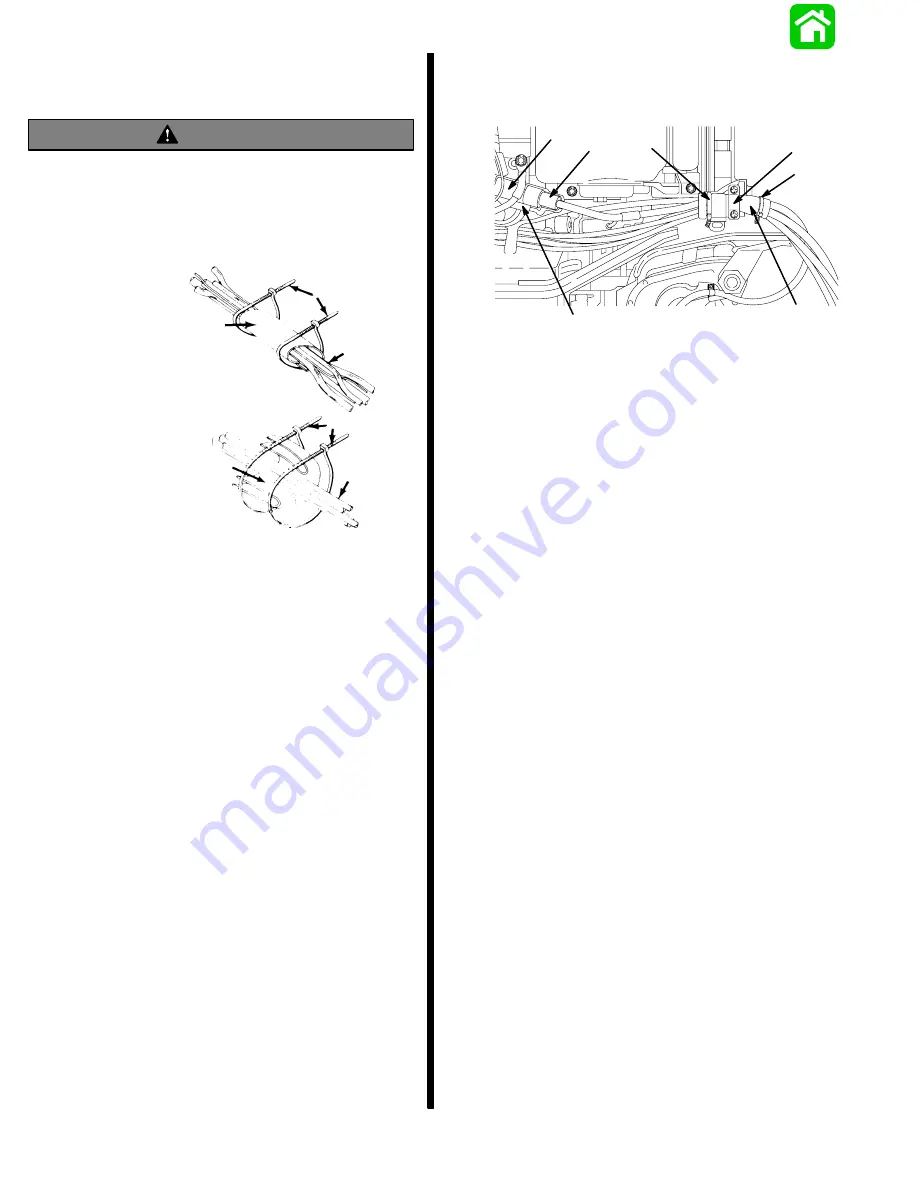
Connecting Engine Wiring Harness
and Routing of Engine Cables
WARNING
Wiring passing through cowl must be protected
from damage by using a neoprene sheet as
shown. Failure to protect wiring could cause
chafing or cuts in wiring resulting in electrical
system failure and/or possible bodily injury.
Models with Power Trim
Models without Power Trim
a
b
c
a
b
c
a - Wiring Harness
b - Neoprene Sheet
c - Sta-Straps
1. Plug remote control harness connector into en-
gine harness connector, then secure connector in
place with retainer as shown.
IMPORTANT: On Models without Power Trim, the
neoprene sheet must be folded once and then
wrapped around cables as shown.
2. Wrap neoprene sheet around cable bundle and
secure each end with a sta-strap. Secure to
bracket with retainer.
a
b
c
d
e
f
20290
f
a - Engine Connector
b - Retainer
c - Harness Connector
d - Harness Retainer
e - Neoprene Sheet
f - Sta-Strap(s)
Models with Power Trim
Summary of Contents for 100
Page 4: ...GENERAL INFORMATION AND SPECIFICATIONS 1 ...
Page 18: ...IGNITION SYSTEM ELECTRICAL AND IGNITION A 2 ...
Page 30: ...11669 BATTERY CHARGING SYSTEM AND STARTING SYSTEM ELECTRICAL AND IGNITION B 2 ...
Page 58: ...22480 TIMING SYNCHRONIZING ADJUSTING ELECTRICAL AND IGNITION C 2 ...
Page 71: ...WIRING DIAGRAMS ELECTRICAL AND IGNITION D 2 ...
Page 86: ...FUEL SYSTEM AND CARBURETION A 3 ...
Page 118: ...OIL INJECTION SYSTEM B 3 ...
Page 127: ...20032 3 CYLINDER ENGINES POWERHEAD A 4 ...
Page 168: ...791 H GEAR HOUSING LOWER UNIT A 5 ...
Page 170: ...5A 1 90 13645 2 1095 LOWER UNIT Notes ...
Page 205: ...MID SECTION LOWER UNIT B 5 ...
Page 207: ...5B 1 90 13645 2 495 LOWER UNIT Notes ...
Page 218: ...SHOCK ABSORBER LOWER UNIT C 5 ...
Page 223: ...17250 DESIGN I SIDE FILL RESERVOIR POWER TRIM A 6 ...
Page 233: ...6A 9 POWER TRIM 90 13645 2 495 Commander Side Mount Remote Control Wiring Diagram ...
Page 268: ...DESIGN II AFT FILL RESERVOIR POWER TRIM B 6 51344 ...
Page 305: ...SINGLE RAM POWER TRIM C 6 51485 ...
Page 309: ...6C 3 90 13645 2 495 POWER TRIM Notes ...
Page 340: ...50099 ENGINE ATTACHMENTS ENGINE INSTALLATION 7 A ...
Page 369: ...TILLER HANDLE AND CO PILOT OUTBOARD MOTOR INSTALLATION ATTACHMENTS 7 B ...
Page 371: ...7B 1 90 13645 2 495 OUTBOARD MOTOR INSTALLATION ATTACHMENTS Notes ...