


4A-22
90-13645--2
495
POWERHEAD
S
Use a bristle brush and carbon remover solution to
remove carbon from side surfaces.
S
A tool can be made for cleaning the inner diameter
of the tapered ring grooves. The tool can be made
from a broken tapered piston ring with the side ta-
per removed to enable inside edge of the ring to
reach the inside diameter of the groove. Carefully
scrape the carbon from inner diameter of ring
grooves. Care must be taken not to damage the
grooves by scratching the surfaces of the grooves.
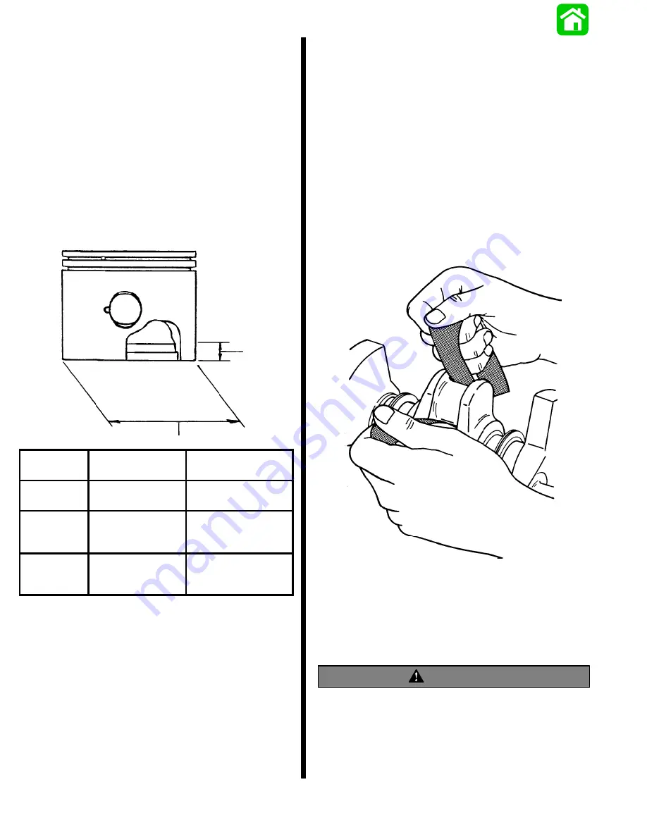
MEASURING PISTON SKIRT
Measure piston skirt at right angle (90
_
) to piston pin
centerline, 0.50 in. (12.7mm) up from bottom edge of
skirt.
.50 in.
(12.7mm)
PISTON
SIZE
PISTON SKIRT
DIAMETER
CYLINDER BORE
FINISH HONE
Standard
Piston
3.371 in.
(85.623mm)
3.375 in.
(85.725mm)
0.015 in.
(0.381mm)
Oversize
3.386 in.
(86.004mm)
3.390 in.
(86.106mm)
0.030 in.
(0.752mm)
Oversize
3.401 in.
(86.385mm)
3.405 in.
(86.487mm)
Crankshaft
S
Inspect crankshaft to drive shaft splines for wear.
(Replace crankshaft, if necessary.)
S
Check crankshaft for straightness. Total maximum
runout for crankshaft is 0.006 (0.152mm). Replace
as necessary.
S
Inspect crankshaft oil seal surfaces. Sealing sur-
faces must not be grooved, pitted or scratched.
(Replace as necessary.)
S
Check all crankshaft bearing surfaces for rust, wa-
ter marks, chatter marks, uneven wear and/or
overheating. (Refer to “Connecting Rods.”)
S
If necessary, clean crankshaft surfaces with cro-
cus cloth as shown.
51089
S
Thoroughly clean (with solvent) and dry crankshaft
and crankshaft ball bearings. Recheck surfaces of
crankshaft. Replace crankshaft if surfaces cannot
be properly “cleaned up”. If crankshaft will be re-
used, lubricate surfaces of crankshaft with light oil
to prevent rust. DO NOT lubricate crankshaft ball
bearings at this time.
WARNING
DO NOT spin-dry crankshaft ball bearing with
compressed air.
Summary of Contents for 100
Page 4: ...GENERAL INFORMATION AND SPECIFICATIONS 1 ...
Page 18: ...IGNITION SYSTEM ELECTRICAL AND IGNITION A 2 ...
Page 30: ...11669 BATTERY CHARGING SYSTEM AND STARTING SYSTEM ELECTRICAL AND IGNITION B 2 ...
Page 58: ...22480 TIMING SYNCHRONIZING ADJUSTING ELECTRICAL AND IGNITION C 2 ...
Page 71: ...WIRING DIAGRAMS ELECTRICAL AND IGNITION D 2 ...
Page 86: ...FUEL SYSTEM AND CARBURETION A 3 ...
Page 118: ...OIL INJECTION SYSTEM B 3 ...
Page 127: ...20032 3 CYLINDER ENGINES POWERHEAD A 4 ...
Page 168: ...791 H GEAR HOUSING LOWER UNIT A 5 ...
Page 170: ...5A 1 90 13645 2 1095 LOWER UNIT Notes ...
Page 205: ...MID SECTION LOWER UNIT B 5 ...
Page 207: ...5B 1 90 13645 2 495 LOWER UNIT Notes ...
Page 218: ...SHOCK ABSORBER LOWER UNIT C 5 ...
Page 223: ...17250 DESIGN I SIDE FILL RESERVOIR POWER TRIM A 6 ...
Page 233: ...6A 9 POWER TRIM 90 13645 2 495 Commander Side Mount Remote Control Wiring Diagram ...
Page 268: ...DESIGN II AFT FILL RESERVOIR POWER TRIM B 6 51344 ...
Page 305: ...SINGLE RAM POWER TRIM C 6 51485 ...
Page 309: ...6C 3 90 13645 2 495 POWER TRIM Notes ...
Page 340: ...50099 ENGINE ATTACHMENTS ENGINE INSTALLATION 7 A ...
Page 369: ...TILLER HANDLE AND CO PILOT OUTBOARD MOTOR INSTALLATION ATTACHMENTS 7 B ...
Page 371: ...7B 1 90 13645 2 495 OUTBOARD MOTOR INSTALLATION ATTACHMENTS Notes ...