


90-13645--2
495
6B-13
POWER TRIM
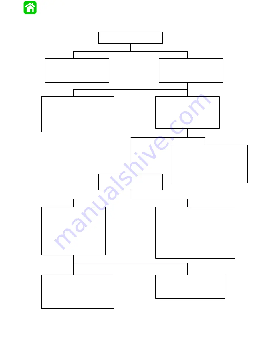
Troubleshooting the “Down” and “Up”
Circuits (All Circuits Inoperative)
Battery Voltage Indicated:
No Voltage Indicated:
Battery Voltage Indicated:
Battery Voltage Indicated:
Battery Voltage Indicated:
No Voltage Indicated:
No Voltage Indicated:
No Voltage Indicated:
Blown Fuse:
Fuse Not Blown:
Check in-line fuses (under cowl) to
see if fuses are blown.
•
Correct problem that caused fuse
to blow.
•
Replace fuse.
•
Check battery leads and RED leads
(between engine starter motor solenoid
and Point 3) for poor connections or
open circuits.
•
Check battery charge.
•
Connect Voltmeter RED lead to
Point 10.
•
Depress “Up” trim button and
check for battery voltage.
•
Check BLACK ground wires at solenoids
for poor connection or poor ground.
•
Check BLACK motor lead for poor
ground at Point 11. If wire is grounded,
the pump motor is faulty. Refer to “Motor
and Electrical Tests/Repair,” following.
•
Check for open in wire.
•
Check for loose or corroded connections.
•
Check for voltage at any instru-
ment, using a Voltmeter.
•
Turn ignition switch to “Run” position.
•
DO NOT start engine.
•
Check for pinched or severed wires.
•
Check all trim harness connectors for loose
or corroded connections.
•
Check trim switch.
Connect Voltmeter RED lead to
Point 3 and BLACK lead to ground.
Battery voltage should be indicated.
There is an open circuit in wire between
Point 5 and RED lead terminal on the
back of the ignition switch.
RED wire is open between Point 12 and red
terminal on back of the ignition switch.
Check that voltage is being supplied
to control by performing the following
checks:
Connect RED Voltmeter lead to
Point 5, and BLACK lead to ground.
Trim switch is faulty or there is an open circuit
in wires [GREEN-WHITE, BLUE-WHITE AND
PURPLE-WHITE (OR PURPLE)] between trim
buttons and trim pump.
Summary of Contents for 100
Page 4: ...GENERAL INFORMATION AND SPECIFICATIONS 1 ...
Page 18: ...IGNITION SYSTEM ELECTRICAL AND IGNITION A 2 ...
Page 30: ...11669 BATTERY CHARGING SYSTEM AND STARTING SYSTEM ELECTRICAL AND IGNITION B 2 ...
Page 58: ...22480 TIMING SYNCHRONIZING ADJUSTING ELECTRICAL AND IGNITION C 2 ...
Page 71: ...WIRING DIAGRAMS ELECTRICAL AND IGNITION D 2 ...
Page 86: ...FUEL SYSTEM AND CARBURETION A 3 ...
Page 118: ...OIL INJECTION SYSTEM B 3 ...
Page 127: ...20032 3 CYLINDER ENGINES POWERHEAD A 4 ...
Page 168: ...791 H GEAR HOUSING LOWER UNIT A 5 ...
Page 170: ...5A 1 90 13645 2 1095 LOWER UNIT Notes ...
Page 205: ...MID SECTION LOWER UNIT B 5 ...
Page 207: ...5B 1 90 13645 2 495 LOWER UNIT Notes ...
Page 218: ...SHOCK ABSORBER LOWER UNIT C 5 ...
Page 223: ...17250 DESIGN I SIDE FILL RESERVOIR POWER TRIM A 6 ...
Page 233: ...6A 9 POWER TRIM 90 13645 2 495 Commander Side Mount Remote Control Wiring Diagram ...
Page 268: ...DESIGN II AFT FILL RESERVOIR POWER TRIM B 6 51344 ...
Page 305: ...SINGLE RAM POWER TRIM C 6 51485 ...
Page 309: ...6C 3 90 13645 2 495 POWER TRIM Notes ...
Page 340: ...50099 ENGINE ATTACHMENTS ENGINE INSTALLATION 7 A ...
Page 369: ...TILLER HANDLE AND CO PILOT OUTBOARD MOTOR INSTALLATION ATTACHMENTS 7 B ...
Page 371: ...7B 1 90 13645 2 495 OUTBOARD MOTOR INSTALLATION ATTACHMENTS Notes ...